2 Mounting and installation
BU 0240 en-US-4920 35
Pos: 16 0 /Anlei tung en/El ektr onik/FU und Star ter/2 . Mon tage un d Install atio n/Elek trisc her Ans chlus s/SK 1xxE, SK 2x xE, S K 5xxP, SK xxxE- FDS/ Steuer teil /Elektr isc her Ansc hlus s Steu erteil [SK 2xxE] @ 20\mod_1513343185610_14638.docx @ 2375937 @ 3 @ 1
2.3.3 Electrical connection of the control unit
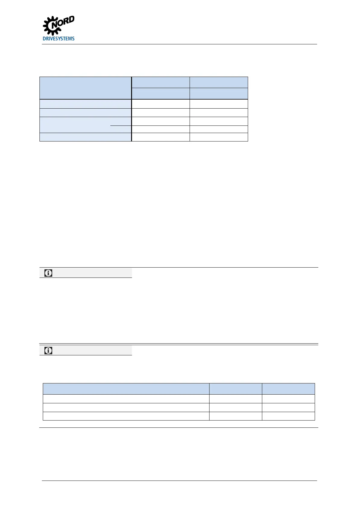
Connection data:
Terminal block Size 1-4 Size 4
[lb-in] 4.42 … 5.31 4.42 … 5.31
* flexible cable with ferrules (with or without plastic collar) or rigid cable
SK 2x0E SK 2x5E
The device generates its own 24 V DC control
voltage and provides this to terminal 43 (for
connecting external sensor systems, for
example).
However, size 4 devices can also be supplied
by an external control voltage source
(connection to terminal 44). The switchover
between the internal
supply unit takes place automatically.
The device must be provided with an external
24 V DC
control voltage. Alternatively, an
optional 24 V DC
SK CU4-… or SK TU4-… can be used.
The control voltage for devices t
AS interface (SK 225E and SK
be supplied via the yellow AS interface line.
However, in this case the variable frequency
drive must not have an additional supply via
terminal 44 in order to prevent damage to the
power supply unit or the AS interface bus.
A control unit overload caused by impermissibly high currents may destroy the unit. Impermissibly high currents
occur if the total current actually obtained exceeds the permissible total current, or if the 24 V DC control voltage
for other devices is passed through the variable frequency drive. Use double ferrules, for example, to avoid
conduction through the variable frequency drive.
The control unit can also be overloaded and destroyed if the 24 V DC supply terminals of devices with an
integrated power supply unit (SK 2x0E) are connected to a different voltage source. For this reason, make sure
that any wires for the 24 V DC power supply are not connected to the device but are insulated accordingly,
particularly when installing connectors for the control connection (example of connector for system bus
connection SK TIE4-M12-SYSS).
24 V DC can be taken from several terminals as necessary. This also includes e.g. digital outputs or an operating
module connected via RJ45.
The sum total of currents obtained must not exceed the following limits:
Device model Size 1 to 3 Size 4
Devices with AS interface, when using the AS interface
 Loading...


