NORDAC FLEX (SK 200E ... SK 235E) – Brief instructions for Frequency Inverters
32 BU 0240 en-US-4920
Pos: 12 1 /Anlei tung en/El ektr onik/FU und Star ter/2 . Mon tage un d Install atio n/Elek trisc her Ans chlus s/Elek tris cher Ans chl uss_0 1 (Übers chrift ) [SK 1xx E, SK 2x xE, SK 5xx E, SK xx xE-FDS, SK 500P, SK300P] @ 12\mod_1467020207250_14638. docx @ 333211 @ 2 @ 1
2.3 Electrical connection
Pos: 12 2 /Anlei tung en/El ektr onik/FU und Star ter/1 . Allg emei nes/Sic herh eits- und Ins tall ations hinwei se un d Warn- Gefahrenhinw eise/neu/War n- und Ge fahre nhinw eise/ WARNU NG - Elek tri scher Sc hlag (S pannu ng, au ch wenn Gerät auß er Betri eb) [d ezen tral auß er FDS] @ 41\mod_1585136481755_14638.docx @ 2599401 @ @ 1
Electric shock
Dangerous voltages can be present at the power input and the motor connection terminals even when
the device is not in operation.
• Before starting work, check whether all relevant components (voltage source, connection cables,
connection terminals of the device) are de-energized using suitable measuring equipment.
• Use insulated tools (e.g. screwdrivers).
• DEVICES MUST BE GROUNDED.
Pos: 12 3 /Anlei tung en/El ektr onik/FU und Star ter/2 . Mon tage un d Install atio n/Elek trisc her Ans chlus s/Elek tris cher Ans chl uss_0 2 [SK 1xxE, SK 2xxE, SK 5xx E; -FDS, S K 50 0P] @ 2 9\mod_1551967877653_14638.docx @ 2499477 @ @ 1
Temperature sensor and PTC thermistor (TF)
As with other signal cables, PTC thermistors must be laid separately from motor cables. Otherwise
the interference signals induced by the motor winding into the line will cause a disturbance in the
device.
Ensure that the device and the motor are specified for the correct supply voltage.
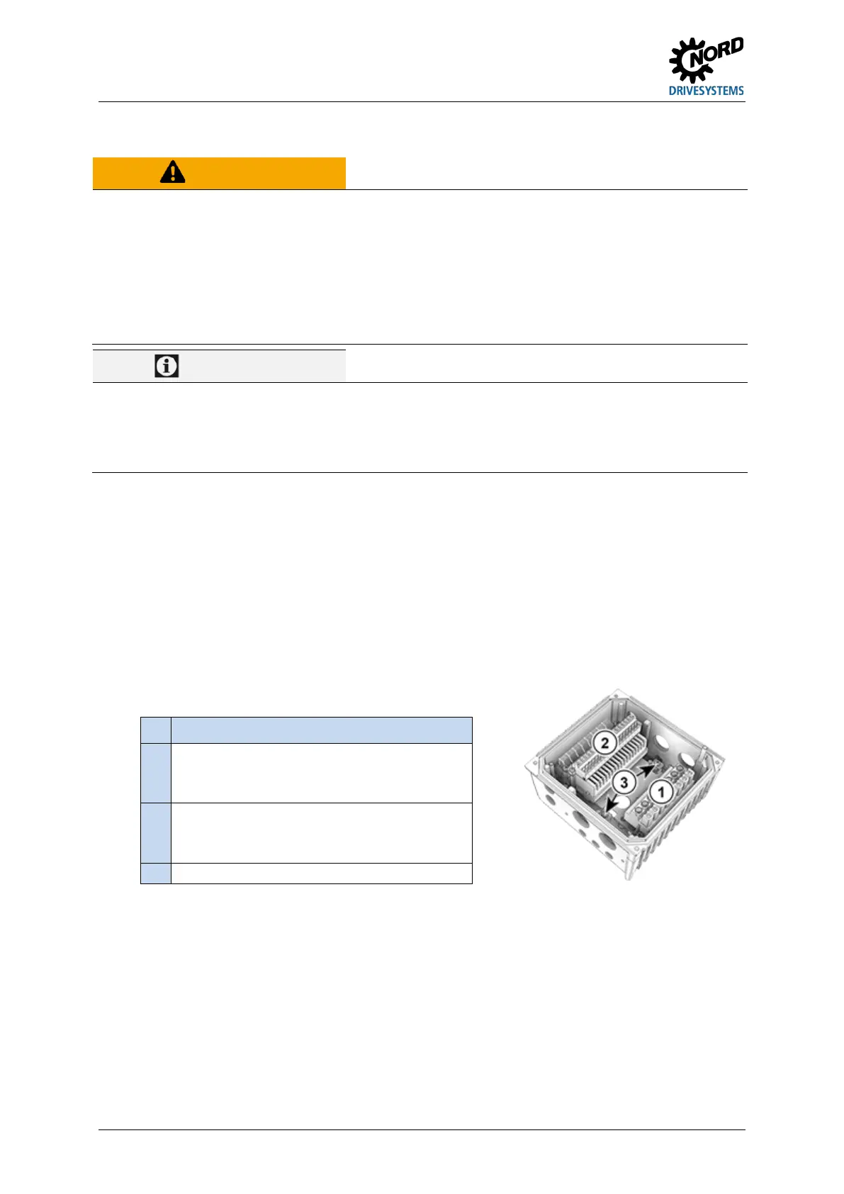
Pos: 12 4 /Anlei tung en/El ektr onik/FU und Star ter/2 . Mon tage un d Install atio n/Elek trisc her Ans chlus s/Elek tris cher Ans chl uss_Er gänz ung 1 [SK 2x xE] @ 7 \mod_1434463656020_14638.docx @ 226136 @ @ 1
In order to establish the electrical connections, remove the SK 2xxE from the SK TI4-... connection
unit ( Section 2.1.2 "Motor installation steps").
One terminal block is provided for the power connections and one for the control connections.
The PE connections (device ground) are inside the cast housing of the connection unit on the bottom.
One contact is available on the power terminal block for size 4.
Pos: 12 5 /Anlei tung en/El ektr onik/FU und Star ter/2 . Mon tage un d Install atio n/Elek trisc her Ans chlus s/Elek tris cher Ans chl uss_Er gänz ung 2 [SK 1x xE, SK 2xx E] @ 8\mod_1439219159130_14638.docx @ 236274 @ @ 1
The terminal block assignments differ according to the version of the device. The correct assignment
can be found on the inscription on the respective terminal or the terminal overview plan printed inside
the device.
Pos: 12 6 /Anlei tung en/El ektr onik/FU und Star ter/2 . Mon tage un d Install atio n/Elek trisc her Ans chlus s/Elek tris cher Ans chl uss_Er gänz ung3 [ SK 2 xxE ] @ 8\mod_1439287784030_14638. docx @ 236374 @ @ 1
Connecting terminals for
PTC thermistor (TF) of motor
PE
Pos: 12 7 /Allg emein/ Allg emeing ültig e Mod ule/---------Sei tenum bruc h k omp akt --------- @ 13\mod_1476369695906_0.docx @ 2265496 @ @ 1
 Loading...


