3 Display, operation and options
BU 0240 en-US-4920 53
Frequenzumrichter
SK 2x5E-...
44
40
.
.
21
22
23
24
.
.
.
L1 - L2/N - L3
115/230/400V
24V Netzteil
SK CU4-24V-...
Steuerklemmenleiste
44 40 44 ... 11 14 12 B1
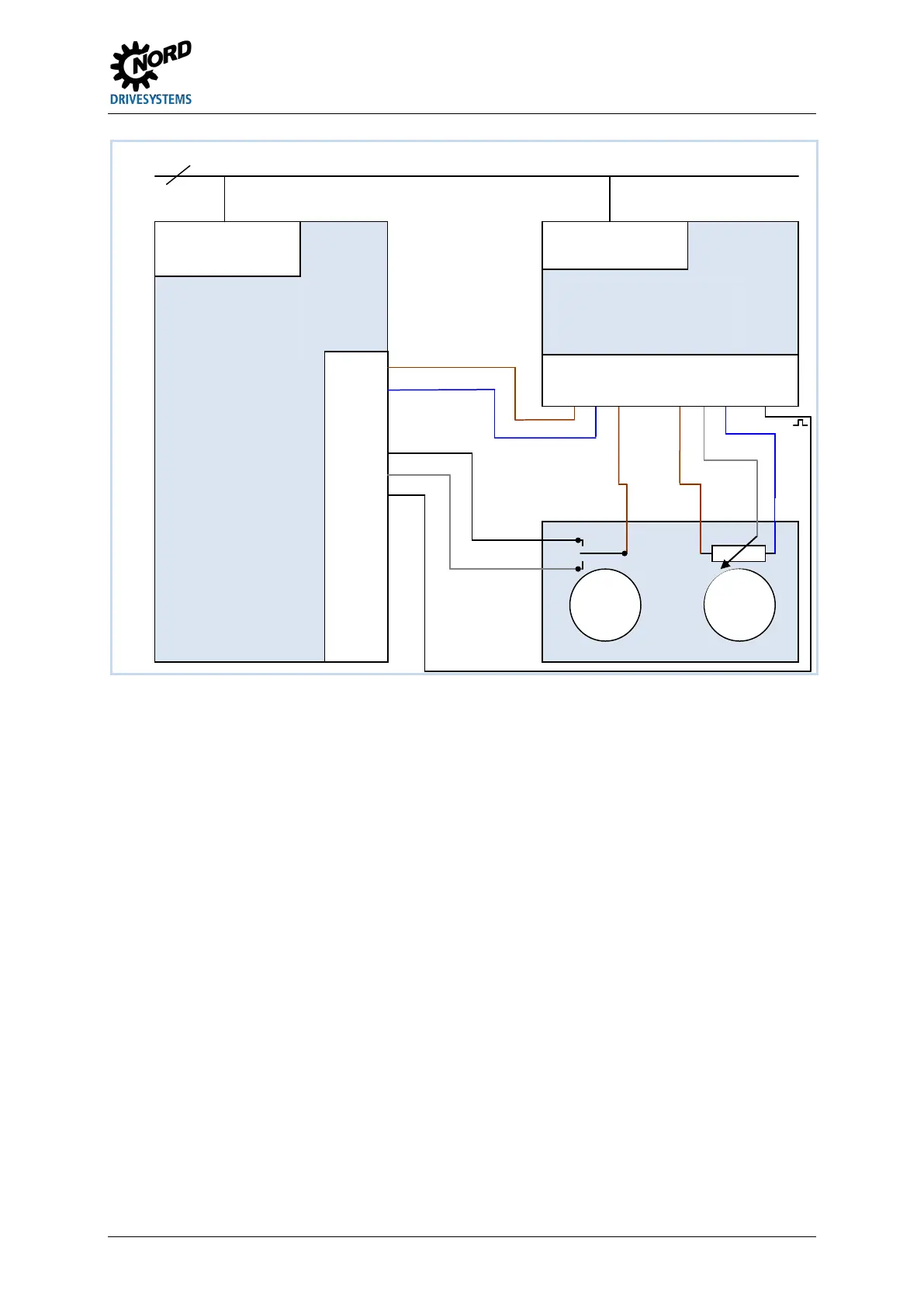
Figure 10: Connection diagram and parameterization of SK CU4-POT, example SK 2x5E
DIP switch settings (S1:): DIP3 = off, DIP4 = on, DIP5 = off (please see chapter 4.2.2.2
"DIP switches (S1)" on page 58)
or
Recommended parameter setting,
S1: DIP1-8 = off
P400 [07] = 1 P420 [02] = 2
P420 [01] = 1 P420 [03]= 26
Pos: 22 1 /Anlei tu nge n/El ektr onik /FU un d St art er/4 . I nbe tri ebn ahme/ SK 1xx E, S K 2x xE, -FD S/In betrie bnahm e (Übers chri ft) [SK 1x xE, S K 2xxE, FD S] @ 1\mod_1343217825591_14638.docx @ 37233 @ 1 @ 1
Variable frequency
drive SK 2x5E
-…
switch
0-10
SK CU4-24V-…
(WH)
 Loading...


