2 Mounting and installation
BU 0240 en-US-4920 25
Pos: 77 /A nl eitu nge n/El ek tro nik/FU u nd S tart er/ 2. M ont age und Ins tall ation/M ont age/M otorm ontag e - Sta ndar d [S K 1xxE , S K 2xx E]/ Arb eits gä nge für die M otor m ontag e [ SK 2xx E] @ 1\mod_1341488911979_14638.docx @ 29976 @ 3 @ 1
2.1.2 Motor installation steps
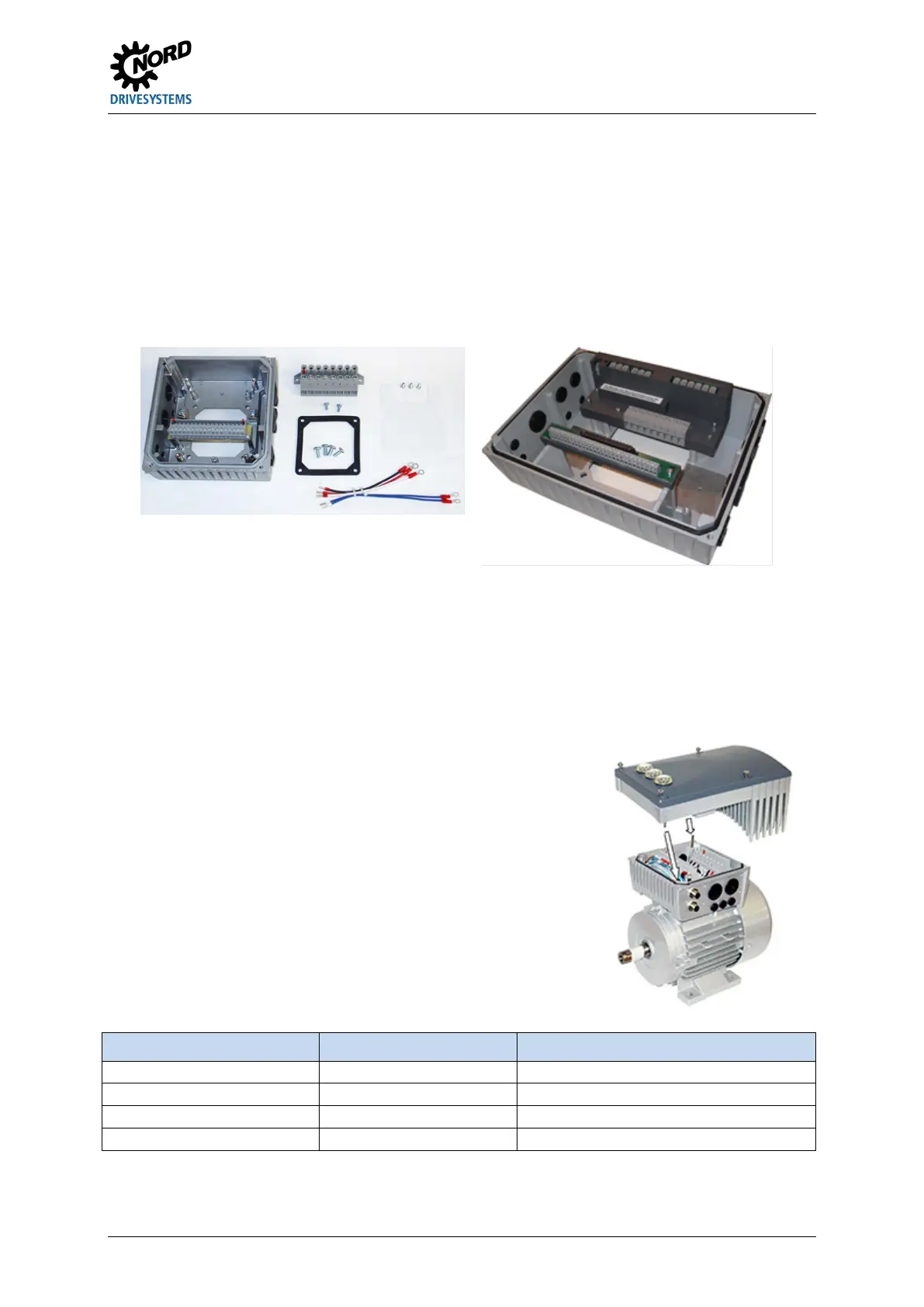
1. If necessary, remove the original terminal box from the NORD motor so that only the base of the terminal
box and the motor terminal block remain.
Place the bridges for the correct motor circuit on the motor terminal block and connect the ready-made
cables for motor and PTC thermistor connections to the respective connection points on the motor.
Mount the connection unit on the terminal box base of the NORD motor using the existing screws and
gasket as well as the enclosed toothed/contact washers. When doing this, align the housing so that the
rounded side is facing in the direction of the A end shield of the motor. Carry out mechanical adaptation
using the adapter kit ( 2.1.2.1 "Adapters for motor size"). In general, check whether motors made by
other manufacturers can be connected.
Figure 2: Connection unit size 1 … 3 Figure 3: Connection unit size 4
Fasten insulating plate above the motor terminal block.
– Size 4: Fasten toroidal core to insulating plate ( Section 2.1.1 "Installation of insulating plate – size
4").
Screw on power terminal block above this using 2x M4x8 screws and the plastic washers (size 4: 3x M4 cap
nuts).
Make electrical connections. Use screwed connections appropriate for cable cross-section for the cable
entry of the connecting cable.
6. Place the variable frequency drive on the
comes to sizes 1 to 3, pay special attention to the correct contacting of
the PE pins. These are located diagonally in 2 corners of the variable
frequency drive and the connection unit.
In order to ensure that the degree of protection for which the device is
intended is achieved, make sure that all fastening screws that attach
the variable frequency drive to the connection unit are tightened
crosswise, step by step and at the torques indicated in the table below.
The cable screw connections used at a minimum must correspond to
the degree of protection of the device.
Size SK 2xxE Screw size Tightening torque
Pos: 78 /A llg em ein/ Allg em eing ülti ge M od ule/ ---------Seite num bruc h kom pak t --------- @ 13 \mod_1476369695906_0.docx @ 2265496 @ @ 1
 Loading...


