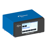
ValveMate 7197PCP-2K Controller
46 www.nordsonefd.com info@nordsonefd.com +1-401-431-7000 Sales and service of Nordson EFD dispensing systems are available worldwide.
Technical Data (continued)
Wiring Diagrams for Connecting the PURGE Initiate Circuit
Sourcing
Sinking
External contact
NO (normally open)
Pin 15: 24 VDC
Pin 9: GND
Pin 11: Purge (-)
Pin 10: Purge (+)
NOTE: The breakout board shown in these diagrams is an optional component available to facilitate wiring
connections to the I/O port. A DB-15 cable is also required. Both components are available in a kit (P/N 7364775).
External contact
NO (normally open)
Pin 15: 24 VDC
Pin 9: GND
Pin 11:
Purge (-)
Pin 10:
Purge (+)

 Loading...