236 Chapter 39 Hardware procedures
NN10600-175 6.1S2
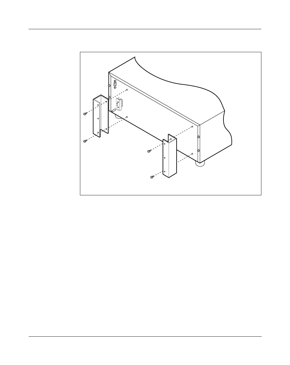
Figure 70
Multiservice Switch 7420 termination panel mounting brackets
2 Position the termination panels so that the top most panel aligns with the
top-most processor card. This arrangement simplifies cable routing.
3 Align the holes at the top and bottom of the termination panel with the
holes on the raised mounting brackets.
4 Loosely fasten the screws to attach the termination panels to the brackets.
See the figure
“Multiservice Switch 7420 termination panel installation” on
page 237.
PPT 3221 007 A
 Loading...