Chapter 39 Hardware procedures 397
Multiservice Switch 7400 Hardware Installation, Maintenance, and Upgrade 6.1S2
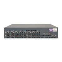
Powering up a Multiservice Switch 7460
Power up a Nortel Networks Multiservice Switch 7460 after you have
installed all plug-in and screw-on parts onto the shelf assembly.
Prerequisites
• Verify that all power supply controls are in the standby position. See the
figure
“The power control on the power supply for a Multiservice
Switch 7460” (page 398).
Procedure steps
1 Unseat all processor cards from the backplane of the shelf.
2 Seat the minimum number of processor cards required, based on the
number of power supplies in the shelf.
If you have one power supply, seat a CP in slot 0 and at least one FP.
Ensure that all other processor cards are unseated.
If you have two power supplies, seat at least one CP and two FPs. Or, seat
two CPs and at least one FP.
3 Toggle on power to the device at the upstream power source.
4 Power up the power supply that is labeled PS1 by toggling its power
control to the on position. See the figure “The power control on the power
supply for a Multiservice Switch 7460” (page 398).
If you have not seated a CP or any FPs before you turn on a power supply,
the system does not supply power to the shelf, and the LED on the power
supply shows green.
5 Verify that the LED on the power supply is green.
6 Verify that the cooling unit LED is green and is operational. You should be
able to hear the fans start to rotate.
7 If present, apply power to the second power supply labeled PS2 by
toggling to the on position its power control. Verify that its LED is green.
8 Seat the remaining processor cards.
9 Verify the LED color on the processor cards is appropriate. See the table
“Processor card LED status display” (page 326).
10 Verify that the appropriate LEDs are illuminated on termination panels.
See
“Termination panel LED status display” (page 393).