Chapter 39 Hardware procedures 287
Multiservice Switch 7400 Hardware Installation, Maintenance, and Upgrade 6.1S2
3 Hold the chassis in place with one hand and use a 5/16-in. socket wrench
to secure the unit to the frame. Use the 4 screws that are taped to the unit.
4 With the assistance of a second person, lift the shelf assembly and set it
on top of the cooling unit chassis.
5 Use a 5/16-in. socket wrench to secure the assembly to the frame. Use
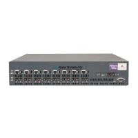
the eight screws that are taped to the unit. See the figure
“Multiservice
Switch 7480 shelf assembly” (page 289).
6 Insert the cable management assembly into the cabinet frame and set it
on top of the shelf assembly. See the figure
“Multiservice Switch 7480
cable management assembly” (page 290).
7 Use a 5/16-in. socket wrench to secure the cable management unit to the
frame. Use the four screws that are provided.
8 With the filter gate facing down, slide the air filter into its slot at the top of
the cooling unit chassis. See the figure “Installing an air filter in a
Multiservice Switch 7480” (page 498). Do not force the air filter into its
slot.
If the air filter assembly is spring loaded, gently press and release the
center of the assembly to fasten it in place.
9 Connect the cooling unit power cord to the connector on the back of the
shelf assembly that is labelled C.U. Power. Use a 1/8-in. screwdriver to
tighten the 2 screws. See the figure
“Cooling unit power cord” (page 501).
The power cord is pre-connected to the cooling unit chassis.