Controls and Switches Product Description
XPIQ PN 51013:C 7/01/03 13
1.5 Controls and Switches
Controls and Switches Located on XPIQ-MB Motherboard
• SW1 Earth Fault Detection - enables or disables the detection of a ground fault
• SW2 Phone Circuits 1 & 2 Wiring Selection - select 2W for two wire Class B (Style Y) or
4W for four wire Class A (Style Z) circuit wiring
• SW3 Phone Circuits 3 & 4 Wiring Selection - select 2W for two wire Class B (Style Y) or
4W for four wire Class A (Style Z) circuit wiring
• SW4 Background Music Volume Control
• Jumpers JP1 & JP2 - used to enable or disable software upgrade for the XPIQ-MB
Controls and Switches Located on XPIQ-SLI Signaling Line Interface Board
• SW1 Rotary Switch - used to set ones digit of starting address on the SLC
• SW3 Rotary Switch - used to set tens/hundreds digit of starting address on the SLC
• SW2 Push-button Switch - used to verify addresses on the XPIQ
• Jumpers JP1 & JP2 - used to enable or disable downloading programming to the XPIQ-SLI
1.6 Basic Components
1.6.1 XPIQ-MB Motherboard
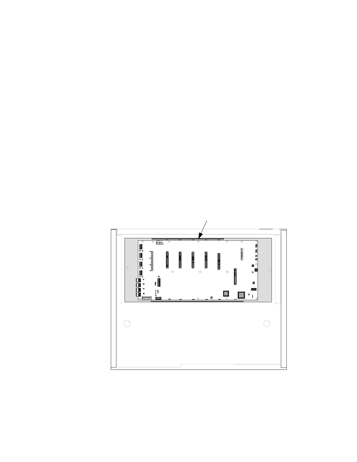
The XPIQ-MB Motherboard is mounted in the backbox with the orientation shown in Figure 1.2
(refer to "Backbox Installation" on page 26 for mounting information).
The XPIQ-MB Motherboard contains a microcontroller, memory, two tone generators, connectors
for option boards and pluggable terminal blocks for field wiring. Standard and optional boards are
mounted to connectors on the motherboard providing easy maintenance and system expansion.
TB1 TB2
TB3
TB4
TB5
TB6 TB7
TB8
J7 J6
J11 J12
J13
TB10
SW4
JP1
JP2
SW1
EARTH FAU LT
DETECTION
EARTH
FAULT
GEN TBL
DISA BL ED
ENA BLED
P6
P5
P4
P3
P2
P1
Low Level
Backup I N
Remote
Out
BCKGND
MUSI C
Remote
In
High Level
Backup IN
High Level
Backup OUT
Low Level
Backup OUT
J9
XPIQ- PS Con trol Cable
XPIQ-PS Power
EXT TRBL IN
SW3
SW2
PHONE
1 AND 2
PHON E
3 AND 4
CHGTRBL
Phone 4 TRB L
Phone 3 TRB L
Phone 2 TRB L
Phone 1 TRBL
Riser TRBL
TRBL
TRBL
TRBL
TRBL
SPKR1
SPKR2
SPKR 3
SPKR 4
BATTRBL
A.C. Fail
J1
J2
J10
J4
J5
J8
Phon e 1
Phon e 2
Phon e 3
Phon e 4
Spkr1
Spkr2
Spkr3
Spkr4
TB9
2 X 2W
2 X 2W
1 X 4W
1 X 4W
PHONE/NAC RISER
XPIQ-C A Option
SHLD - PH + SHLD - PH +
+ OUT - S HLD + OU T - SHLD
+ OUT - SHLD + OUT - SHLD
CONTROL/COMM
AUD IO I N
AMP LIF IER #4
AMP LIFIE R #3
AMPLIFIER # 2
AMPLIFIER #1
1 2
1 2 3 4 5 6
S - + S - + S - + S - +
123 123 123
1 2 3
1 2 31 2 3 1 2 3 1 2 3
5
6
7
8
9
0
1
2
3
4
Figure 1.2 XPIQ-MB Orientation in Backbox
XPIQ-MB Motherboard
CAB-A3/CAB-A3B Backbox
Top edge of motherboard when installed in backbox
XPIQ-CAB.CDR