Switch and Jumper Settings Installation
XPIQ PN 51013:C 7/01/03 53
2.6 Switch and Jumper Settings
2.6.1 XPIQ-SLI Signaling Line Interface
2.6.1.1 Addressing - SW1 and SW3 Rotary Switches
The first address assigned to the XPIQ is termed the ‘Base Address’. The base address is a
three-digit number which can be set for any value up to the maximum number of addresses
allowable on the Signaling Line Circuit (SLC) by the FACP (from 001 to 159 for FlashScan
mode, or 01 to 99 for CLIP mode). When setting this base address, keep the following points
in mind:
✓ The base address, which is set with SW1 and SW3 rotary switches, plus any additional
addresses assigned to the XPIQ circuits by the motherboard, may not be used by any other
device on the SLC.
✓ The base address cannot be set to a number that would exceed 159 or 99, depending on the
FACP used, when all the addresses consumed by the XPIQ are added to the base address.
For example, if an XPIQ consumes 20 addresses plus the base address, the setting for the
base address could not exceed 139 (139 + 20 = 159) for a panel that uses 159 addresses.
✓ All addresses are sequential, beginning with the base address, with no gaps
✓ PK-XPIQ software, which is used to program the XPIQ, will assign the various points to
the sequential addresses, beginning with the base address.
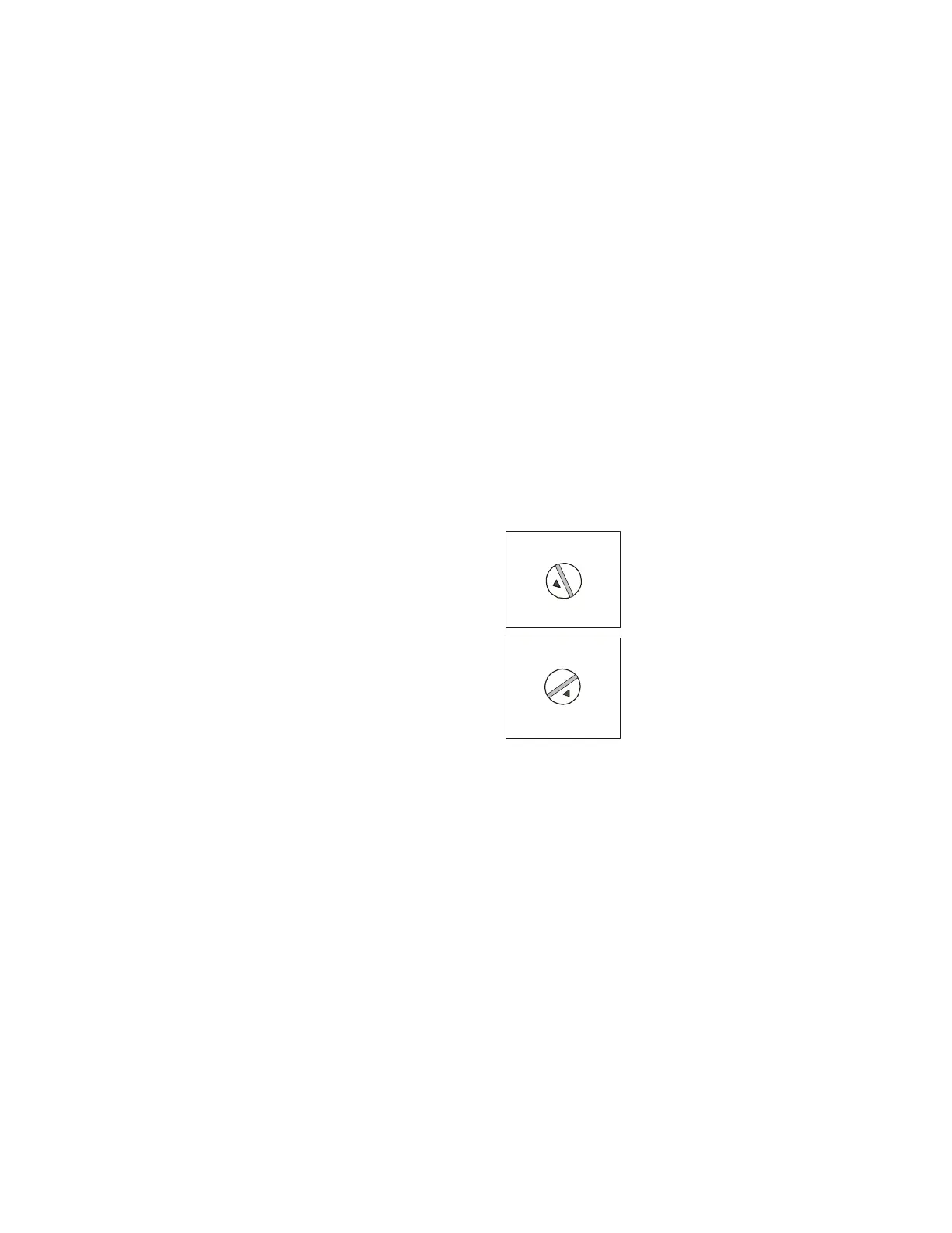
Figure 2.30 XPIQ-SLI Rotary Switches
To set the base address of the XPIQ, turn switch SW3 (Tens Address) until the arrow on the
switch points to the number corresponding to the most significant digits (tens or hundreds/tens
digits) of the address. Turn switch SW1 (Ones Address) until the arrow on the switch points
to the number corresponding to the least significant digit (ones digit) of the address.
The base address setting illustrated in Figure 2.30 is 114. The arrow on SW3 (Tens Address)
is pointing to ‘11’ and the arrow on SW1 (Ones Address) is pointing to ‘4.’
All remaining addresses on an XPIQ system are automatically assigned by the motherboard in
increasing order starting from the base address. The amount of the remaining addresses that
will be consumed by an XPIQ system depends upon the number of channels and the number
of speaker zones being used in the system.
TENS ADD
ONES ADDR
SW3
SW1
0
1
2
3
5
9
10
1
1
1
3
1
4
1
5
6
7
8
4
12
0
1
9
8
7
6
2
3
4
5
XPQADDSW.CDR