Basic Components Product Description
XPIQ PN 51013:C 7/01/03 19
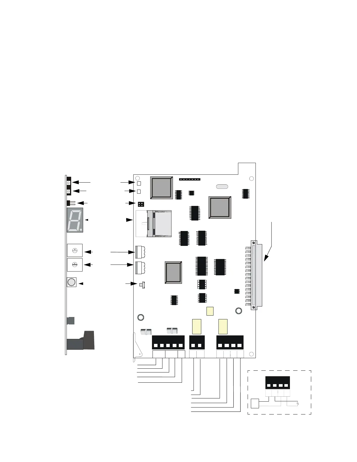
1.6.4 XPIQ-SLI Signaling Line Interface Board
The XPIQ-SLI board provides data communication interface between the XPIQ-MB and the SLC
(Signaling Line Circuit) of an FACP (Fire Alarm Control Panel). This board acts as a collection of
control modules and is designed to use either CLIP protocol or the FlashScan protocol. The
number of addresses utilized by the XPIQ-SLI depends on the number of channels, speaker zones,
telephone zones and other options selected during configuration by the installer. Two rotary
switches are used to set the starting address of the board. A seven-segment display is used to
indicate the address range used, when the address verification push-button (SW2) is pressed. The
routing of the audio channels to speaker zones is implemented by activating SLC output points in a
matrix programmed in the XPIQ. The rows of this matrix represent audio input channels and the
columns of this matrix represent speaker circuits. Refer to Table 2.4 through Table 2.19.
The XPIQ-SLI can be wired to the SLC in Style 4, 6 or 7. When configured for Style 4 wiring, the
XPIQ-SLI can be utilized to take advantage of the unique degraded mode operation that takes place
when SLC communication with the FACP is lost. When in degraded mode, the XPIQ-SLI
monitors specific FlashScan detectors/monitor modules and automatically activates the evacuation
signal on all speaker zones when an alarm state is detected. Separate alarm contacts on TB3 can be
used as an alternate way of communicating a local alarm condition during degraded mode back to
the FACP. (See TB3 inset in the figure below.)
TROUBLE
ONLINE
TENS ADDR
ONES ADDR
SW3
SW1
SW2
JP1
JP2
J1
+ -
SLCA
+ -
SLCB
54
321 2
1
SLC -
LOCAL
SLC +
LOCAL
ALARM
OUT
ALARM
OUT
ALARM
IN
ALARM
IN
EARTH
GND
P1
TB1
TB2
TB3
+
+
-
-
0
1
2
3
5
9
1
0
1
1
1
3
1
4
1
5
6
7
8
4
12
0
1
9
8
7
6
2
3
4
5
ALARM
OUT
ALARM
OUT
ALARM
IN
ALARM
IN
TB3
Figure 1.7 XPIQ-SLI Signaling Line Interface
On Line LED
P1 Connector
to motherboard
P6 Connector
Trouble LED
Jumpers JP1
& JP2
7-Segment LED
Address Display
Address
Verification Push-
button Switch
+ SLC A (TB1-5)
- SLC A (TB1-4)
+ SLC B (TB1-3)
- SLC B (TB1-2)
Earth Ground (TB1-1) - Connect
supplied grounding cable to backbox
+SLC for Local Input Devices (TB2-2)
- SLC for Local Input Devices (TB2-1)
General Alarm In + (TB3-4)
General Alarm Out + (TB3-3)
General Alarm In - (TB3-2)
General Alarm Out - (TB3-1)
View of Component Side
Side View
Address Rotary
Switches
Tens
Ones
+
+
-
-
FACP
ELR
+
-
IDC