Installation Switch and Jumper Settings
60 XPIQ PN 51013:C 7/01/03
2.6.1.3 SW2 Push-button Switch
Switch SW2 is used to verify the addresses programmed into the
XPIQ. Pressing SW2 will cause the address to be displayed one
digit at a time on the 7-segment LED display.
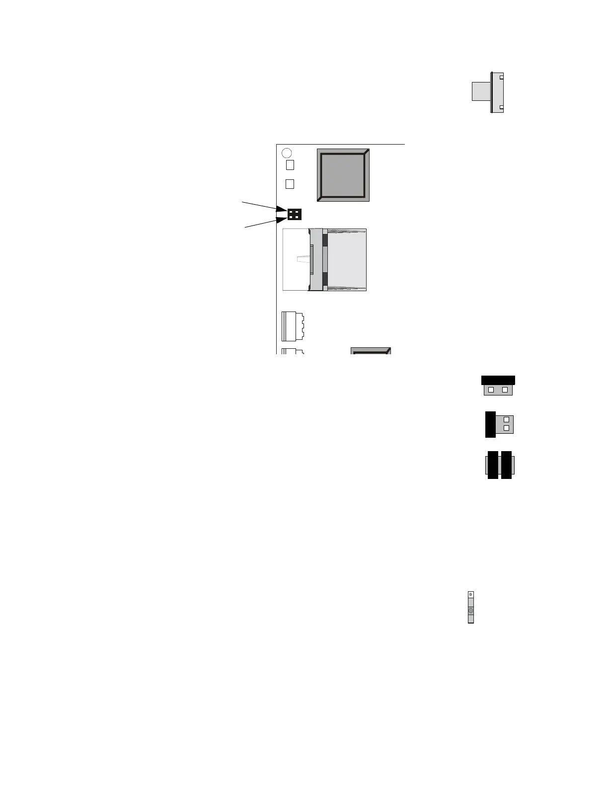
2.6.1.4 JP1 & JP2 Jumpers
Jumpers JP1 and JP2 are used to enable and disable XPIQ-SLI software upgrade:
✓ Normal - Disable XPIQ-SLI software upgrade - Jumper JP1 Pin 1 to JP2
pin 1 (factory default setting)
✓ Enable Software Upgrade - XPIQ-SLI reprogramming or upgrade of the
Flash memory (system program data) - Jumper JP1 pin 1 to JP1 pin 2
✓ Enable Boot Upgrade - When upgrading the Boot Sector, the PC will
prompt for insertion of jumpers (shunts) as follows: - Jumper JP1 pin 1
to JP1 pin 2, and jumper JP2 pin 1 to JP2 pin 2. The PK-XPIQ gives the
programmer the option of changing the XPIQ’s boot code.
NOTE: The boot code allows the application software to function and would not be changed under
normal circumstances. It would become necessary to alter the boot code only when future hardware
additions or changes require substantial differences in the mechanism for downloading. In this case,
instructions will be supplied for altering the boot code.
2.6.2 XPIQ-MB Motherboard
2.6.2.1 SW1 Slide Switch - Earth Fault Detection
The Earth Fault Detection circuit monitors all wiring and various
circuits for a ground fault condition (low resistance to ground). The
detection circuit can be enabled to monitor for ground faults by
placing switch SW1 in the Enabled position. The switch to the right
is illustrated in the Enabled position.
The detection circuit can be disabled from monitoring for ground faults by placing switch
SW1 in the Disabled position. The ground fault detection circuit might be disabled for
systems with components that have their own detection circuits. Only one ground fault
detection circuit can be enabled in interconnected components. Note that Earth Fault
Detection must also be enabled in programming. This acts as a safety feature since ground
fault programming and SW1 switch position must agree or a trouble will be generated.
SW2
XPQSLIS2.CDR
TROUBLE
ONLINE
TENS ADDR
ONES ADDR
SW3
JP1
JP2
Pin 1
Pin 2
XPIQ-SLI
XPQslip.CDR
JP1JP2
11
2
2
JP1
JP2
11
2
2
JP1
JP2
11
2
2
SW1
EARTH FAULT
DETECTION
DISABLED
ENABLED
XPIQS1.CDR