Switch and Jumper Settings Installation
XPIQ PN 51013:C 7/01/03 61
2.6.2.2 SW2 Slide Switch - Phone Circuits 1 & 2 Wiring
Telephone/NAC circuits 1 & 2 can be configured as two Class B
(Style Y) circuits or one Class A (Style Z) circuit. Switch SW2 is
used to configured the circuits as follows:
Class B (Style Y) - place SW2 in the 2W position (2 wire)
Class A (Style Z) - place SW2 in the 4W position (4 wire)
as illustrated in the figure to the right
2.6.2.3 SW3 Slide Switch - Phone Circuits 3 & 4 Wiring
Telephone/NAC circuits 3 & 4 can be configured as two Class B
(Style Y) circuits or one Class A (Style Z) circuit. Switch SW3 is
used to configured the circuits as follows:
Class B (Style Y) - place SW3 in the 2W position (2 wire)
Class A (Style Z) - place SW3 in the 4W position (4 wire)
as illustrated in the figure to the right
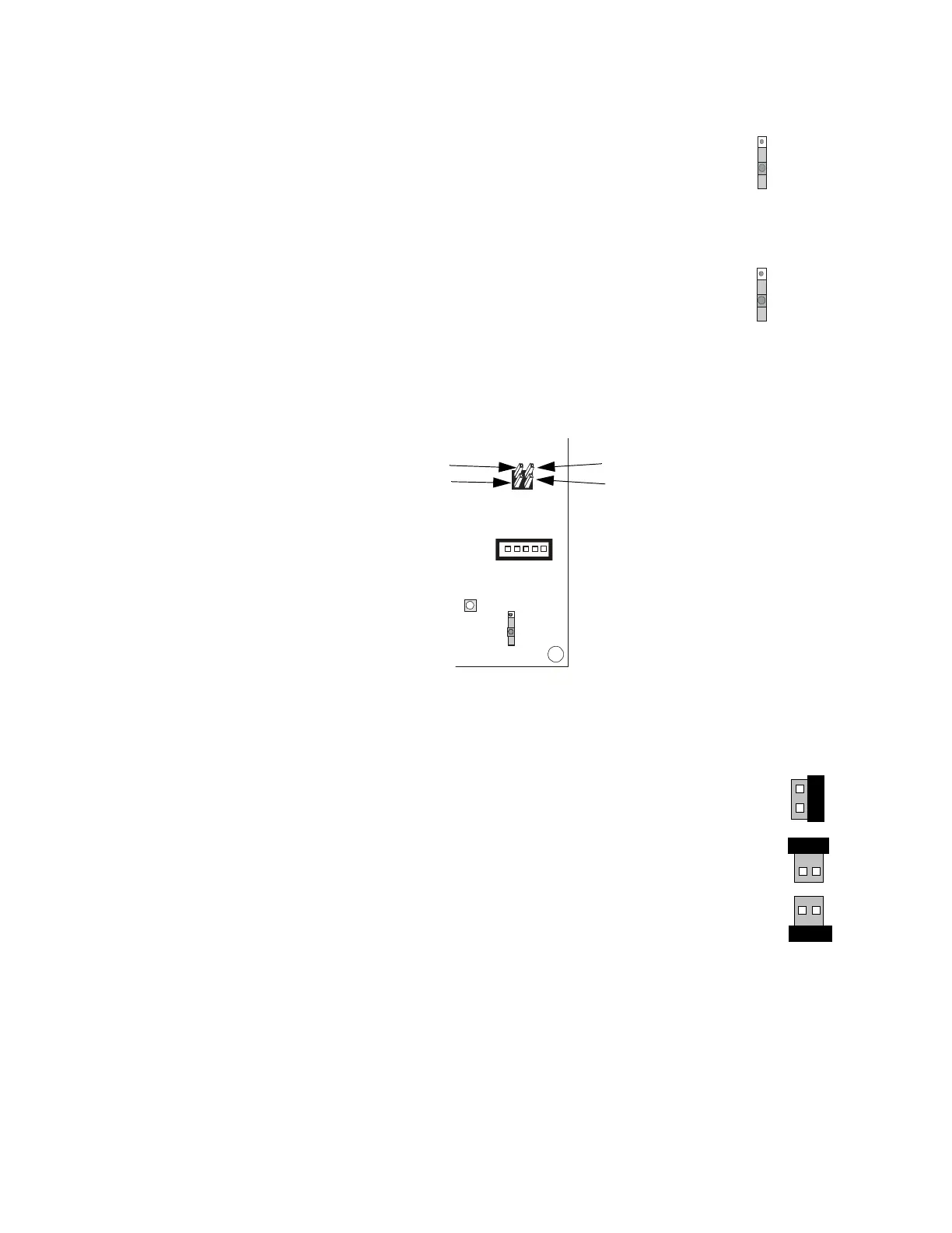
2.6.2.4 JP1 & JP2 Jumpers
Jumpers JP1 and JP2 are only used to enable or disable the software upgrade of the XPIQ-MB
motherboard. The jumper must remain in the Normal position during XPIQ programming
configuration. The following describes the shunt (jumper) positions:
✓ Normal - Disable XPIQ-MB software upgrade
Jumper JP1 Pin 1 to JP2 pin 1 (factory default setting)
✓ Enable Software Upgrade - Enable XPIQ-MB software upgrade
Jumper JP1 pin 1 to JP1 pin 2
✓ Enable Boot Upgrade - Enable XPIQ-MB reprogramming or upgrade
of the Boot Sector memory (boot file)
Jumper JP2 pin 1 to JP2 pin 2
SW2
PHONE
1 AND 2
2 X 2W
1 X 4W
XPIQS2.CDR
SW3
PHONE
3 AND 4
2 X 2W
1 X 4W
XPIQS3.CDR
J13
TRBL RELAY
N/O
JP1
JP2
SW1
EARTH FAULT
DETECTION
EARTH
FAULT
DISABLED
ENABLED
2 1
XPIQ-MB
JP1, Pin 2
JP2, Pin 2
JP1, Pin 1
JP2, Pin 1
XPIQJP1.CDR
JP1
JP2
1
1
2
2
JP1
JP2
1
1
2
2
JP1
JP2
1
1
2
2