Circuit Connections Installation
XPIQ PN 51013:C 7/01/03 43
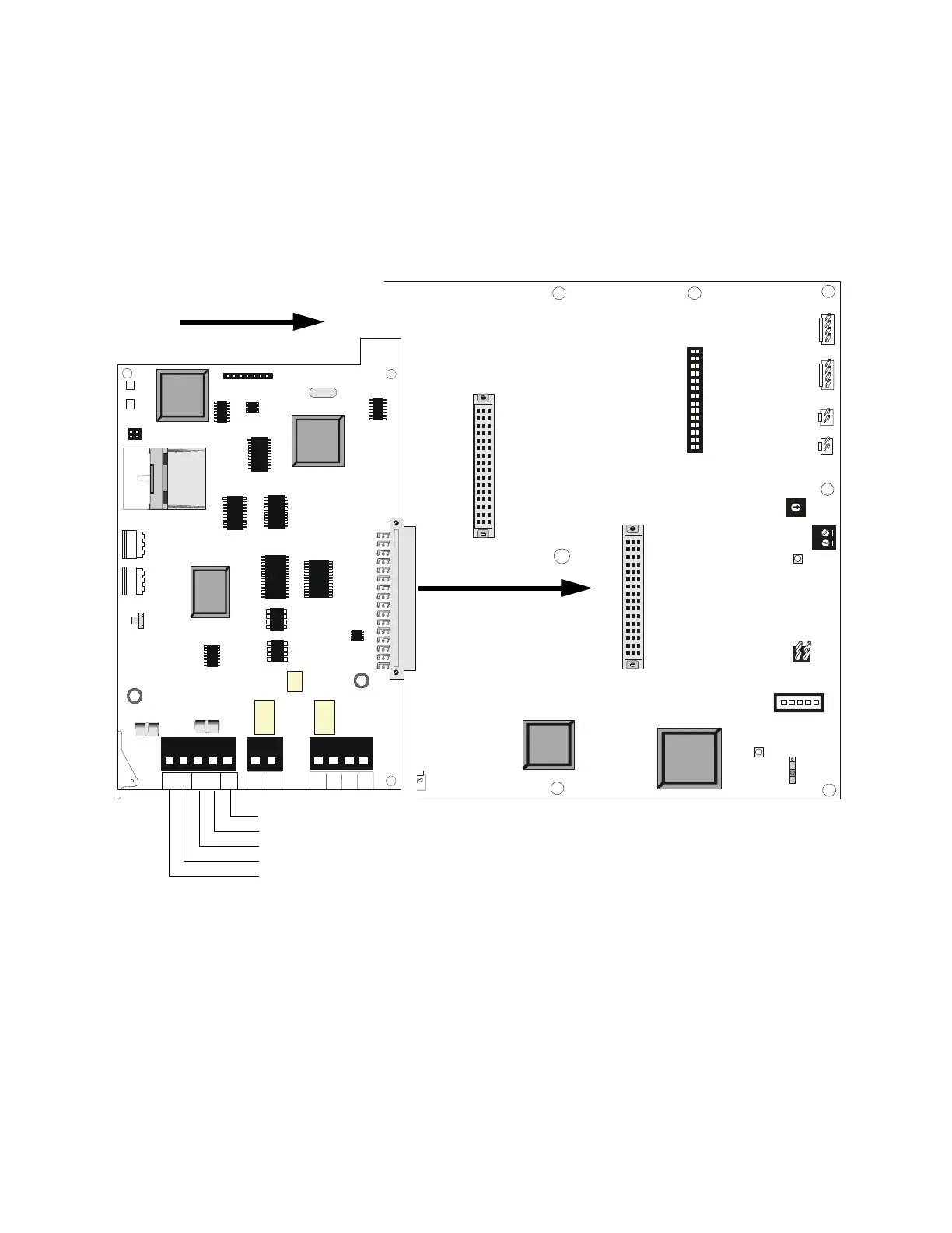
2.5.3 XPIQ-SLI Signaling Line Interface Board
The XPIQ-SLI plugs into connector P6 on the XPIQ-MB motherboard. The SLI provides a Style 4
(Class B), Style 6 or Style 7 (Class A) interface for the SLC (Signaling Line Circuit) which allows
communication between the XPIQ Transponder and host FACP (Fire Alarm Control Panel).
Rotary switches on the XPIQ-SLI are used to set the transponder address for SLC communication.
The XPIQ-SLI receives and transfers commands to the XPIQ-MB motherboard to operate
individual XPIQ points, such as speaker zones, telephone circuits, etc.
J7
J6
J11 J12
J13
TB10
SW4
JP1
JP2
SW1
EARTH FAULT
DETECTION
EARTH
FAULT
GEN TBL
DISABLED
ENABLED
P6
P5
Low Level
Backup IN
Remote
Out
Remote
In
BCKGND
MUSIC
Low Level
Backup OUT
J9
EXT TRBL IN
J8
CONTROL/COMM
AUDIO IN
12
5
6
7
8
9
0
1
2
3
4
TROUBLE
ONLINE
TENS ADDR
ONES ADDR
SW3
SW1
SW2
JP1
JP2
J1
+ -
SLCA
+ -
SLCB
54
321 2
1
SLC -
LOCAL
SLC +
LOCAL
ALARM
OUT
ALARM
OUT
ALARM
IN
ALARM
IN
EARTH
GND
P1
TB1
TB2
TB3
+
+
-
-
Figure 2.18 XPIQ-SLI Signaling Line Interface Board
XPIQ-MB
XPIQ-SLI
XPIQ-SLI mounts at right angle to XPIQ-
MB. Component side of XPIQ-SLI faces in
the direction indicated by the arrow below.
Earth Ground (use supplied grounding cable PN #71073 to connect this screw terminal to the backbox)
SLC B (-)
SLC B (+)
SLC A (-)
SLC A (+)
XPIQSLI.CDR
XPQMBtop.CDR