Installation Circuit Connections
30 XPIQ PN 51013:C 7/01/03
2.5 Circuit Connections
All illustrations of connectors, jumpers and switches in this section are oriented to reflect their
position when the XPIQ-MB motherboard and option modules are correctly mounted in the
backbox.
2.5.1 XPIQ-MB Motherboard Wiring and Cabling
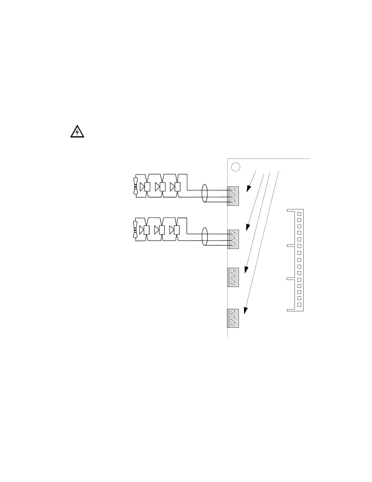
Notification Appliance (Speaker) Circuits - TB1 through TB4
Four Class B (Style Y) speaker circuits are available at TB1, TB2, TB3 and TB4 on the
motherboard. Each supervised and power-limited circuit requires a separate Audio Amplifier.
All speaker circuits are supervised at all times whether the circuit is active or inactive. Refer
to the Notifier Device Compatibility Document for a listing of compatible speakers.
WARNING: High voltages are present at these terminals when the corresponding audio
amplifier is an XPIQ-AA2270.
TB1
J10
TB2
TB3
TB4
+
-
+
-
+
-
+
-
4.7K ohm, 2 watt ELR resistor , P/N: 75603 UL
listed (Style Y, Class B Only)
Speaker Circuits
XPIQ-MB Motherboard
Unused Speaker Circuit
Figure 2.4 Speaker Circuits
Unused Speaker Circuit
Connector
for XPIQ-CA
Do not install an ELR on
unused speaker circuits.
XPIQnac.CDR
Shield
Shield
Shield
Shield