Circuit Connections Installation
XPIQ PN 51013:C 7/01/03 31
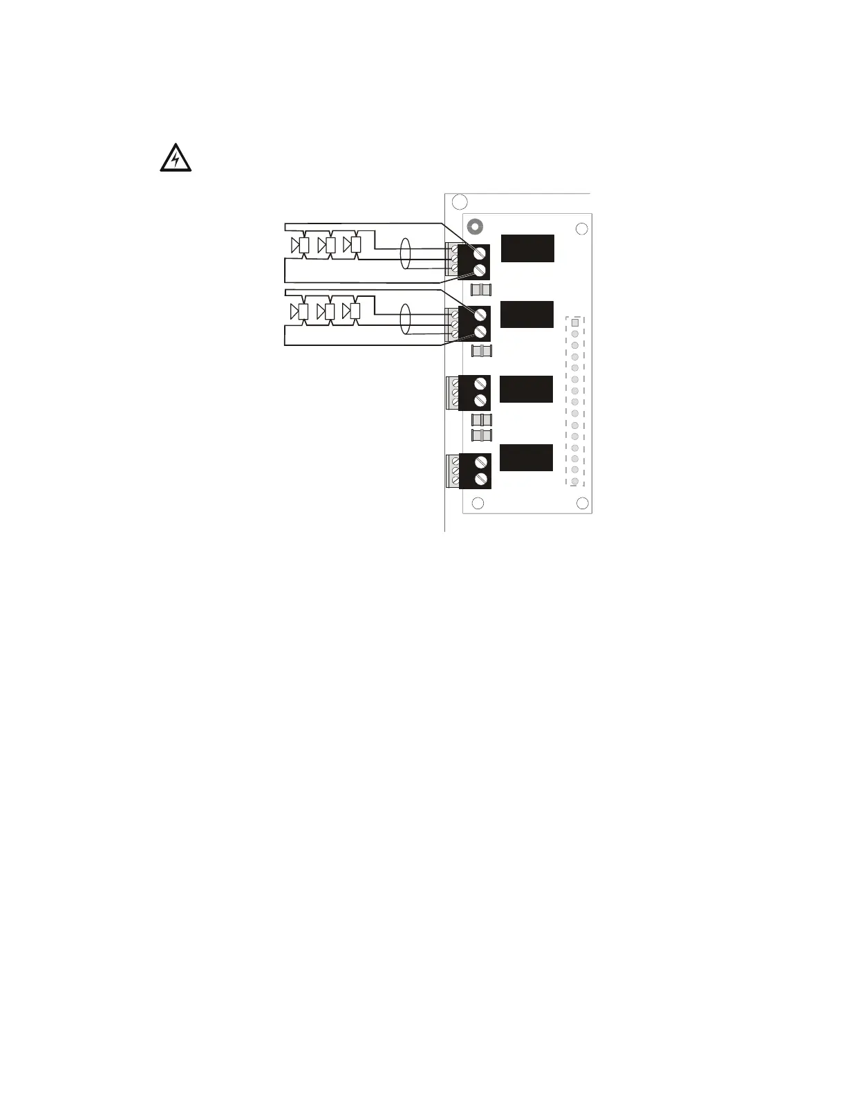
An optional XPIQ-CA Class A Converter Module can be plugged into connector J10. This
module allows the conversion of the four Style Y (Class B) speaker circuits to four Style Z
(Class A) speaker circuits. Refer to Figure 1.11 on page 24 for information on installing the
XPIQ-CA Class A Converter Module on the XPIQ-MB motherboard.
High voltages are present at these terminals when the corresponding audio amplifier is
an XPIQ-AA2270.
Firefighter Telephone/NAC Circuits - TB5 through TB8
Four supervised and power-limited telephone/NAC circuits are provided at Terminal Blocks
TB5, TB6, TB7 and TB8. Twisted-pair cable should be used for telephone circuit wiring.
Figure 2.6 illustrates examples of a Style Y circuit and a Style Z circuit.
IMPORTANT: Do not mix Styles on any one XPIQ. All telephone circuits must be wired as
either up to four Style Y or up to two Style Z circuits.
+
-
+
-
+
-
+
-
P1
TB1
TB2
TB3
TB4
SPEAKER 1
SPEAKER 2
SPEAKER 3
SPEAKER 4
Figure 2.5 XPIQ-CA Class A Converter Module
Do not install jumpers or ELRs on
unused speaker circuits.
XPIQnaca.CDR
Shield
Shield
Shield
Shield
XPIQ-MB