Basic Components Product Description
XPIQ PN 51013:C 7/01/03 17
XPIQ-PS(E) LEDs
The green ON-LINE LED is normally on with AC power applied. Upon AC power fail, the LED
will turn off. The green Boost LED is normally off when the amplifiers are in standby (not active).
When an alarm condition occurs, the amplifiers will activate and the Boost LED will turn on.
Secondary Power Source
The XPIQ-PS(E) includes a charger designed for 24 VDC lead-acid, gel cell batteries (set of two 12
VDC batteries), with a capacity range of between 12 Ah and 25 Ah (ampere-hour). The secondary
source of power may be either a dedicated battery or battery backed-up external source of 24 VDC.
Care must be taken when wiring an external secondary source. Use appropriate wire gauge with
low enough resistance to ensure that the minimum voltage on the XPIQ-PS(E) battery terminals,
with 10 amperes peak current, is no less than 20 volts. Use separate conduit for nonpower-limited
wiring.
When connecting a secondary source, it is important that primary (AC) power be applied first.
After applying AC power, wait until the green AC Power LED turns on before connecting the
secondary power source. This may take up to ten seconds.
CHS-PS Power Supply Chassis
The optional CHS-PS power supply chassis allows installation of the XPIQ-PS(E) power supply in
the upper tiers of the cabinet.
CHS-BH Battery Holder
The CHS-BH battery holder attaches to the CHS-PS. It can hold two 12 V, 12 Ah batteries.
Note that the newer version dress panel (P/N: DP-1B, which is offset) must be used when the
CHS-BH battery holder is installed to the CHS-PS chassis.
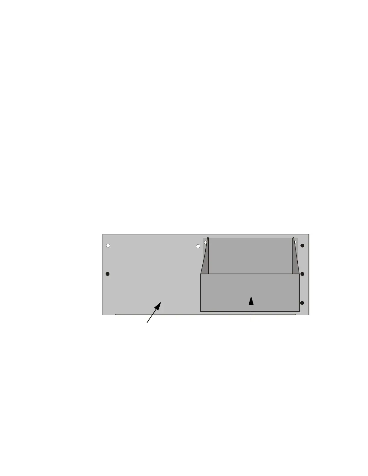
Figure 1.5 CHS-PS Chassis with CHS-BH
CHS-PS Chassis
CHS-BH Battery Holder
XPIQpsch.CDR