Circuit Connections Installation
XPIQ PN 51013:C 7/01/03 33
Notes:
1. Strobe Circuits require termination with ELR-47K resistors supplied with XPIQ-MB
2. Alarm polarity is shown for the Strobe Circuits
3. 2A maximum current is available for each Strobe Circuit
4. 6A total maximum current is available from J9 of the APS-6R
5. When audible NAC devices are needed use coded horns with temporal pattern
WARNING: When using Class A NAC circuits, program the XPIQ for Class A NACs prior to
connecting field wiring to TB5, TB6, TB7, and TB8. Failure to do so may result in damage to
NAC circuitry on the XPIQ-MB
J5
J9 J2 J1
TB2
J3J4
Earth Neut Hot
F2
F1
J8
JP2 JP3
TB3
TB1
+
+
TB4
TB5
TB6
TB7
TB8
J9
XPIQ-P S Control Cable
XPIQ-P S Power
EXT TRBL IN
SW3
SW2
PHONE
1 AND 2
PHONE
3 AND 4
CHGTRBL
Phone 4 TRBL
Phone 3 TRBL
Phone 2 TRBL
Phone1 TRBL
Riser TRBL
TRBL SPKR4
BATTRBL
A.C.F ail
J1
J2
Phone 1
Phone 2
Phone 3
Phone 4
Spkr4
TB9
2 X 2W
2 X 2W
1 X 4W
1 X 4W
+ OUT - SHLD
1 2 3 4 5 6
S - +
S - + S - + S - +
1 2 3
1 2 31 2 3
1 2 3 1 2 3
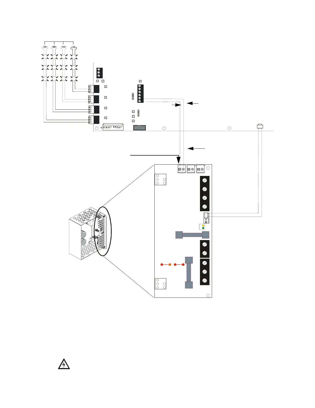
Figure 2.7 APS-6R Powering XPIQ Riser
XPIQ-MB
APS-6R
APS-6R Circuit Board
Trouble Out
External Trouble In
Power Out
NAC Power Input
ELR-47K
(+) Red Wire
connects to
(-) Phone Terminal
(-) Black Wire
connects to
(+) Phone
Terminal
Cable P/N:75121 supplied
with XPIQ-MB
(+)
(+)
(+)
(+)
(-)
(-)
(-)
(-)
Strobe Circuits
Alarm Polarity Shown
NAC Outputs are power-limited
J9 connector is nonpower-limited 24
V, 6 A output (not available on older
supplies). Only the J9 output can be
used as a source of power for
individually short-circuit- protected
strobe circuits. For this application,
do not use J2 or J1.
Cable P/N:71033
XPIQAPS6.CDR