Circuit Connections Installation
XPIQ PN 51013:C 7/01/03 35
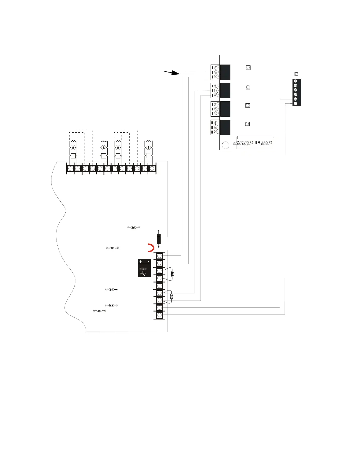
Notes:
1. 47k ohm ELRs must be used to terminate the FFT/NAC from the XPIQ
2. Earth fault detection can remain enabled on both the XPIQ-MB and FCPS-24(E)s
3. Polarity of Aux. Power connections to Phone Riser are the reverse of the silk screen
markings on the XPIQ-MB for this NAC application
4. Polarity of NAC connections to FCPS-24 are the reverse of the silk screen markings on the
XPIQ-MB for this application
5. For a list of compatible devices, refer to the Device Compatibility Document
6. When audible NAC devices are needed, use coded horns with temporal pattern
++
+
+
+ + + + +
++ ++
++
+
+ + + + +
TB3
JP2
D31
9
8
7
6
5
4
3
2
1
R175
R176
R63
TB4
XPIQ-PS Power
Tele4 TRBL
Te l e3 T RB L
Te le 2 T RB L
Te le 1 T RB L
J1
TB5
TB6
TB7
TB8
Phone 1
+
+
+
+
+
+
+
-
-
-
-
-
-
-
Phone 2
Phone 3
Phone 4
1 2 3
1 2 3
1 2 3
1 2 3
Riser TRBL
TB9
Phone
PHONE
NAC
ISE
SHLD - PH + SHLD - PH +
1 2 3 4 5 6
Figure 2.8 XPIQ Control of FCPS-24
XPIQ-MB Motherboard
FCPS-24 Power Supply
*Use listed ELR (P/N: R-2.2K) to terminate Style Y NAC on the
FCPS-24. ELRs are not required when Style Z return is wired.
Note: All Notification Appliance Circuits are supervised.
Style Y*
Style Y*
Style Y*
Optional Style
Z Return
Optional Style
Z Return
Refer to Specifications section of FCPS-24
Manual for current ratings.
Control
Input #2
ELR-
47K
Remaining FFT/NAC
outputs on XPIQ-MB may
be connected to additional
FCPS-24s (maximum of
four when XPIQ is using
the FCPS-24 Aux. Power
connection depicted in
this drawing).
Control
Input #1
FCPS-24 supervision only on
first circuit in this configuration
See Note 3
on polarity
See Note 4
on polarity
ELR-47K
XPIQFCPS.CDR