APPENDIX B OEM729 Technical Specifications
OEM7 Installation and Operation User Manual v1 142
B.6 OEM729 Interface Connectors
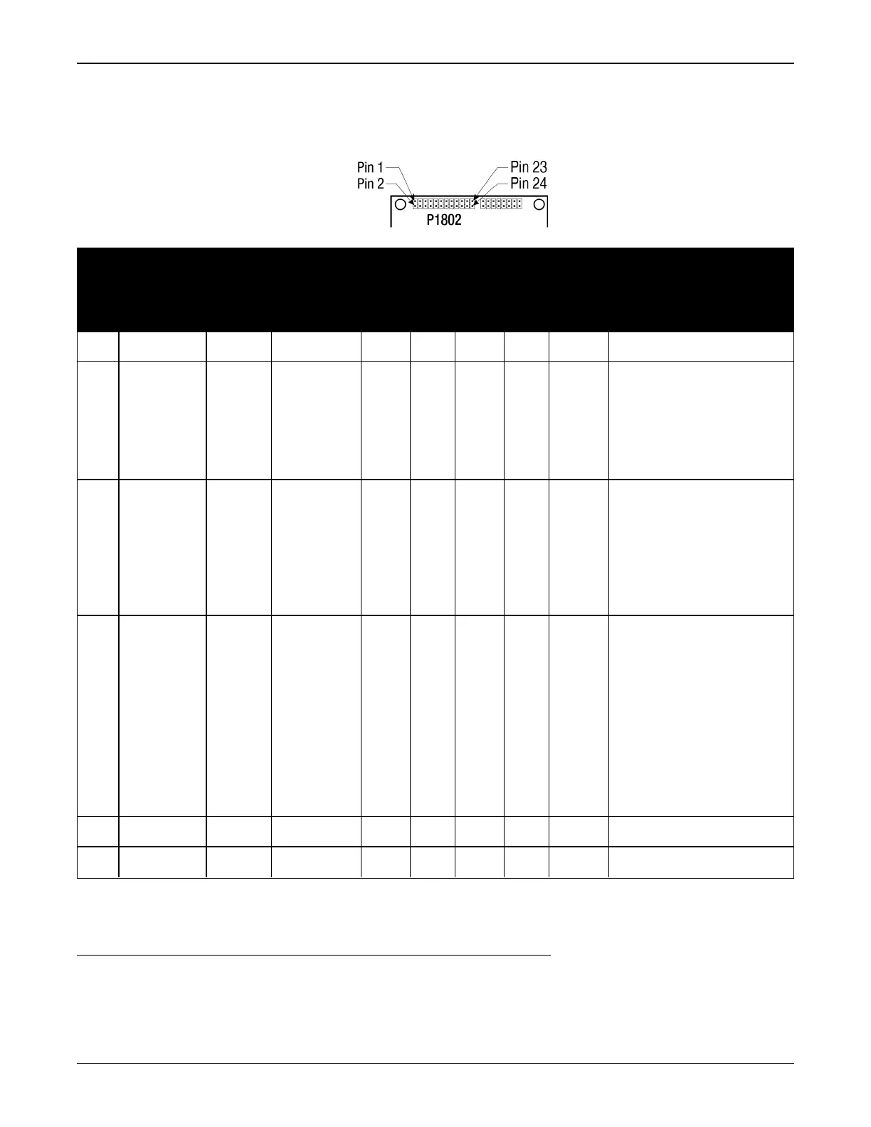
B.6.1 P1802 Main Connector 24-Pin Header
Pin
Signal
Name
Signal
Type
Signal
Direction
V
IL
Max
(V)
V
IH
Min
(V)
V
OL
Max
(V)
V
OH
Min
(V)
Drive
(mA)
Description
1 GND PWR - - - - - - Ground reference
2 USER1
1
3.3V
CMOS
Input/
Output
0.7 2.1 0.4 2.9 4
User GPIO.
May be accessed
through the API
2
Internal 10 kΩ
pulldown.
3 VARF
3.3V
CMOS
Output - - 0.4 2.9 4
Variable Frequency
output
Edges can be
synchronized to the
GNSS time reference.
Internal 10 kΩ pullup
4 PPS
3.3V
CMOS
Output - - 0.55 2.4 16
Pulse Per Second output
This signal defaults to
one pulse per second
but may be altered
across a wide range of
frequencies using
software commands.
Edges can be
synchronized to GNSS
time reference.
5 3V3 PWR - - - - - - 3.3 V ±5% supply input
6 3V3 PWR - - - - - - 3.3 V ±5% supply input
1
On power up, if pin 2 is set LOW or not connected, COM1 will be configured as RS-232. If pin 2 is set high then
COM1 will be configured as RS-422
2
API functionality will not be available until the fourth quarter of 2017



 To Next Page