Chapter 4 Built-In Status Tests
OEM7 Installation and Operation User Manual v1 76
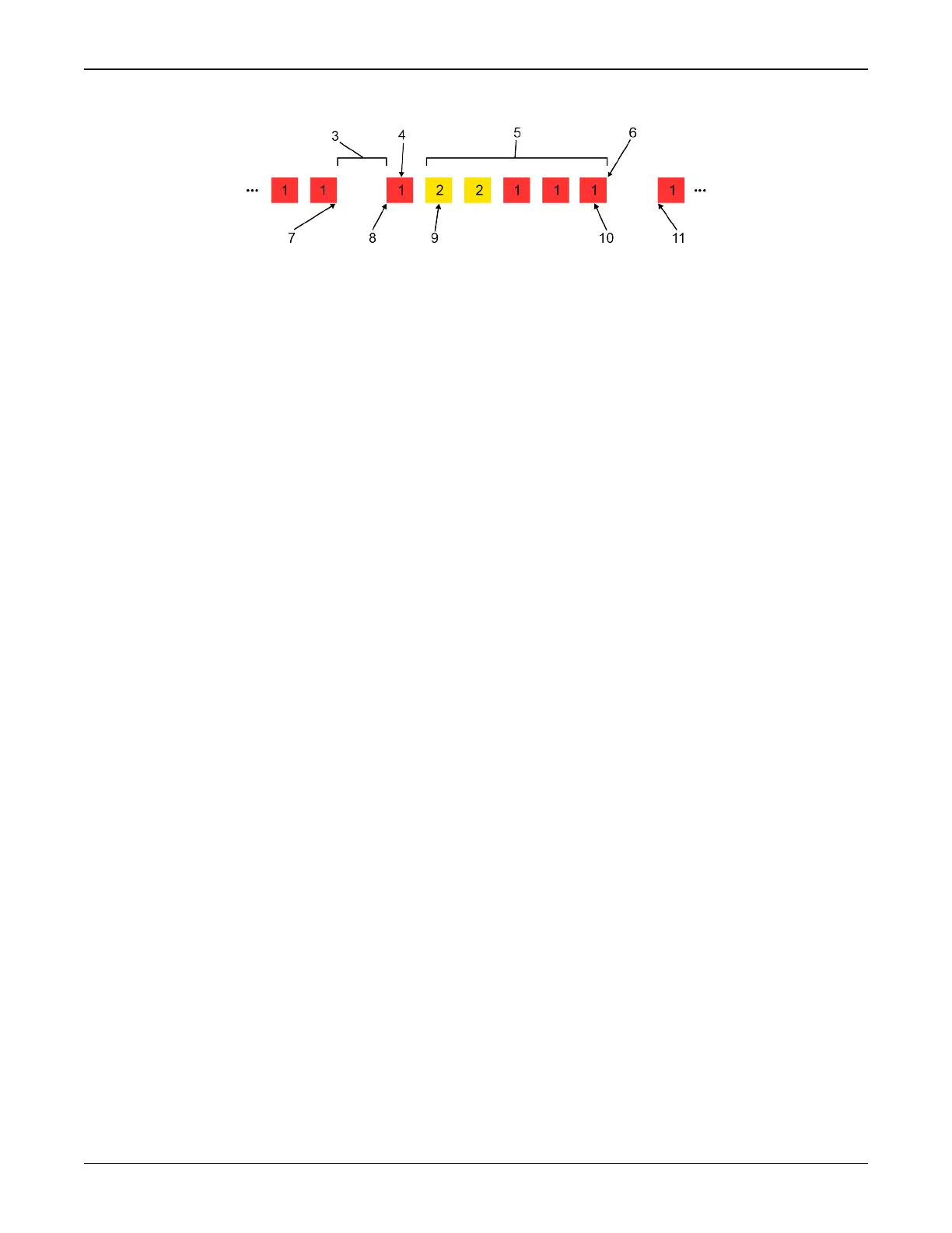
Figure 31: Status LED Flash Sequence Example
Reference Description
1 Red
2 Yellow
3 1 Second Pause
4 Word Identifier Flash
5 Bit Identifier Flashes
6 End of Sequence
7 End of Previous Sequence
8 Beginning of Sequence
9 Most Significant Bit of Binary Value
10 Least Significant Bit of Binary Value
11 Start of Next Sequence
Refer to the RXSTATUS log and associated tables in OEM7 Commands and Logs Reference
Manual (OM-20000169) for more information about this log and receiver error status.


 To Next Page