Display System Utilization
en-938821/2 4 - 13
4
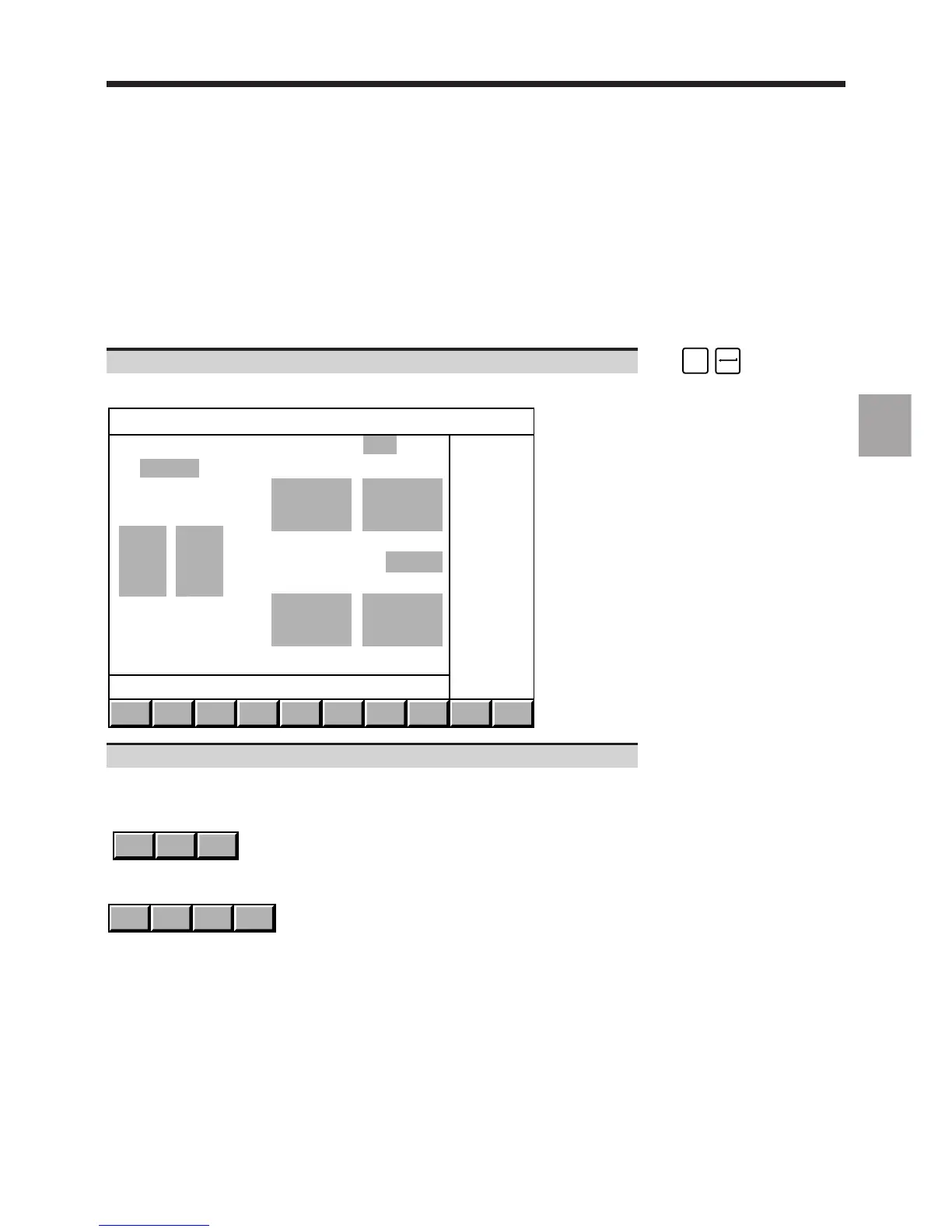
4.6.1 Selection of Graphic Display Parameters and Part Contour Trace
4.6.1.1 Selection of Graphic Display Parameters
Requirements
"GRAPHIC - PROGRAMMING" menu displayed (See 4.6).
Actions
Select "GRAPHIC DISPLAY PARAMETERS". ☞
)
0
Display of the graphic display parameters page:
3D
MODEL
TRACE
PLANE 1
TRACE
PLANE 2
SCALE
1 + 2
EXIT
Program PLANE 1 X-Y
Min. Max.
+0. -+0.
Block +0. -+0.
-
- PLANE 2 from: BELOW
- Min. Max.
+0. -+0.
+0. -+0.
Use the arrow keys to move the cursor to the fields to be completed.
When the following fields are selected, the corresponding softkeys are displayed:
- field "PLANE 1",
Y - Z Z - XX - Y
- field "PLANE 2".
RIGHT ABOVE BELOWLEFT