Display System Utilization
en-938821/2 4 - 15
4
4.6.1.2 Part Contour Trace
Requirements
Graphic display parameters page displayed.
Programme to be displayed selected (See 4.6.1.1).
Actions
Select the plane trace. ☞
TRACE
PLANE 1
or
TRACE
PLANE 2
Automatic scaling of selected plane.
Display of the tool path trace:
SIMULN.
TRACE
ZOOM
AREA
OUT
X : -61.202 162.202 Y + 25.4 - 145.0
1
Y
X
Prog %20
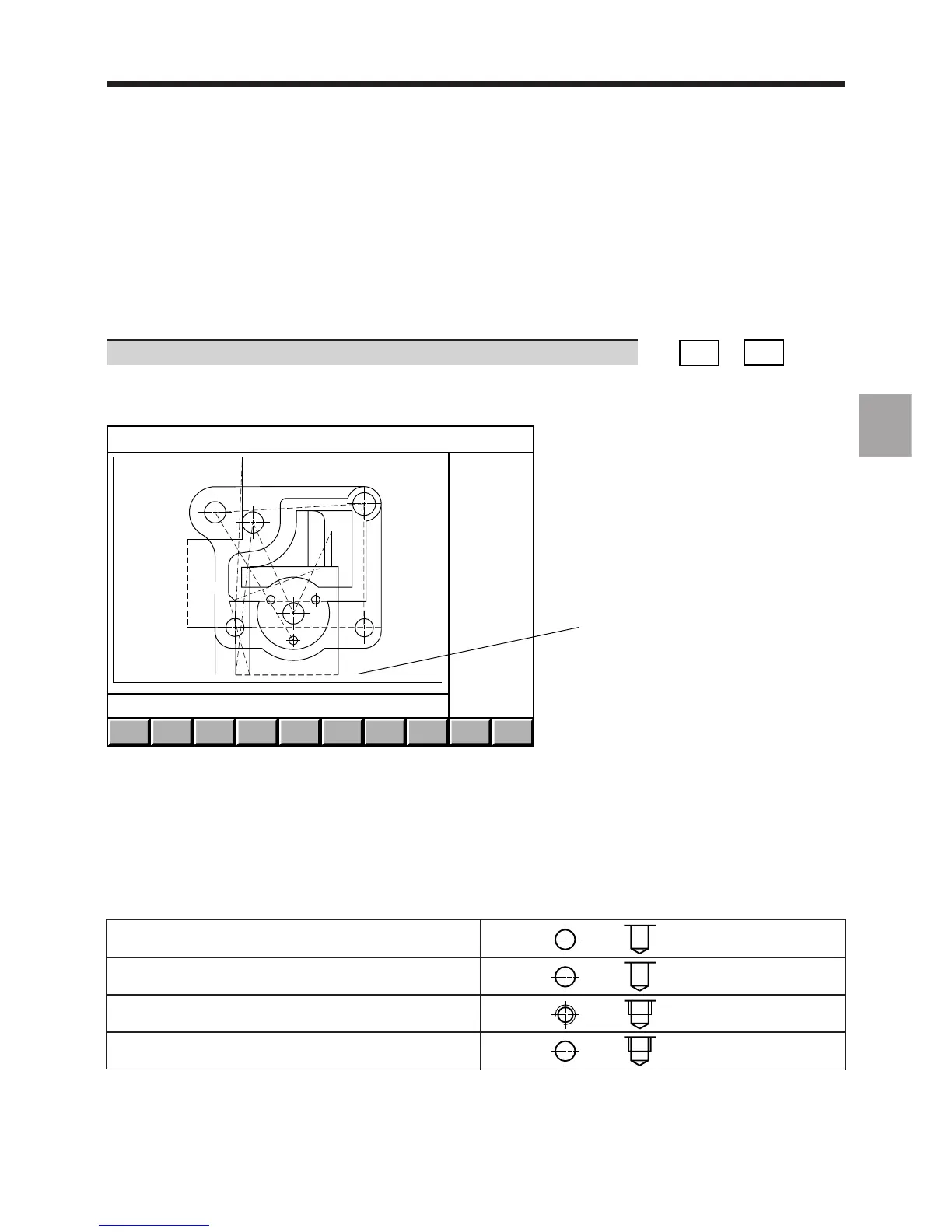
1 - Screen sizing
The tool path trace softkeys allow access to the machining simulation function (See 4.6.2).
The tool paths are drawn:
- as broken lines for rapid movements in function G00,
- as unbroken lines for feed movements in functions G01, G02 and G03.
The cycles are represented by the following symbols proportional to the dimensions of the tool correction used:
Drilling function G81 or G82
Peck drilling function G83 or
drilling with chip breaking function G87
Tapping function G84
Boring functions G85, G86, G88 or G89