USB, PCIe, and UFS
Jetson AGX Xavier Series Product DG-09840-001_v2.5 | 57
7.3 UFS
Jetson AGX Xavier supports a x1 lane UFS interface.
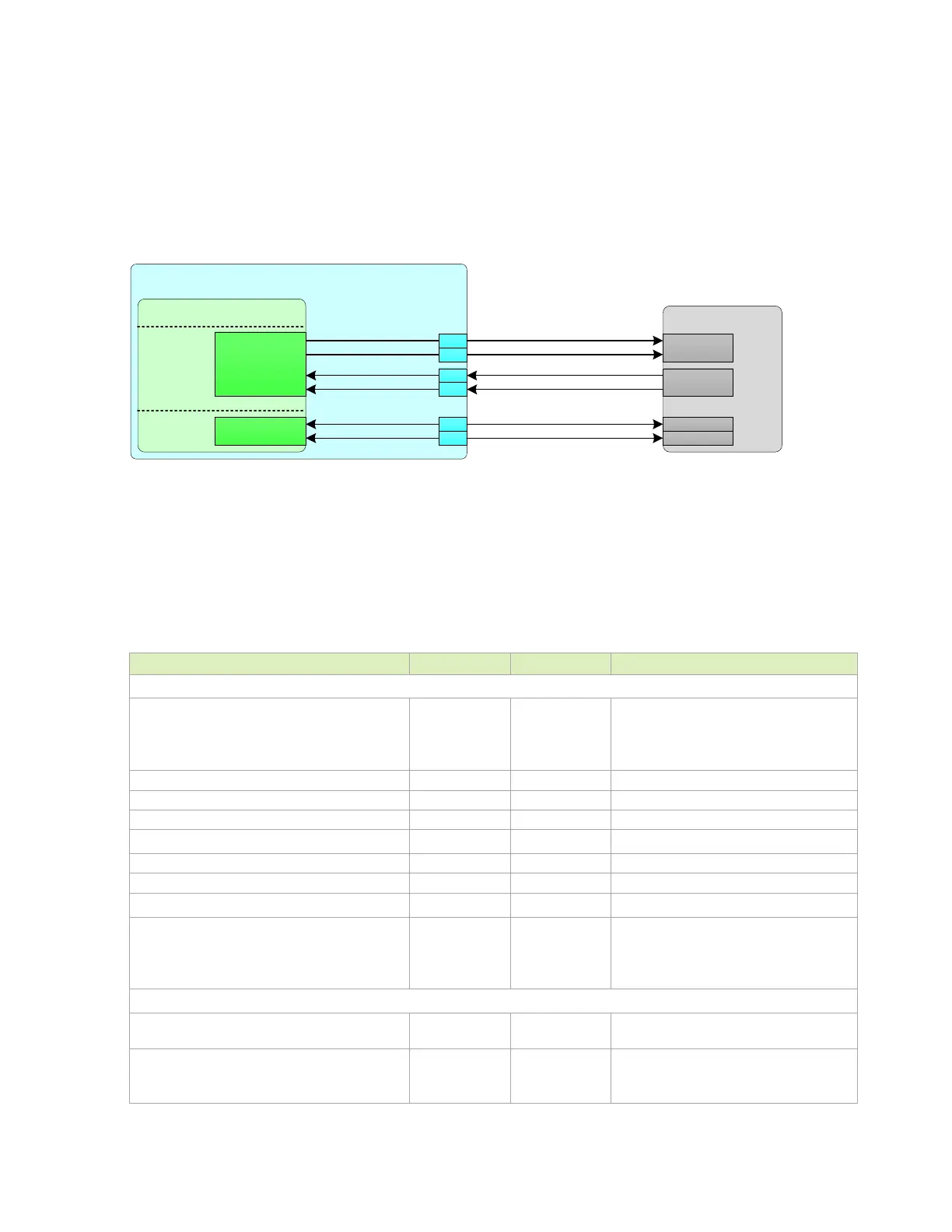
Figure 7-7. UFS Connections Example
Jetson AGX Xavier
SoC
UFS CTRL
UFS0_REF_CLK
UFS0_RST
A6
C6
USB 3.1
PCIe
UFS
PEX_TX10_N
PEX_TX10_P
PEX_RX10_N
PEX_RX10_P
U PH Y _T X 10 _ N
U PH Y _T X 10 _ P
UPHY_RX10_N
UPHY_RX10_P
UFS0_REF_CLK
UFS0_RST_N
K13
K12
B1 2
B1 3
UFS Device
DIN0_T
DIN0_C
DOUT0_T
DOUT0_C
REF_CLK
RESET
UFS_TX 1_ P
UFS_TX 1_ N
UFS_RX 1_P
UFS_RX 1_N
7.3.1 UFS Design Guidelines
The following tables gives the signal routing requirements for the UFS interface.
Table 7-17. UFS Interface Signal Routing Requirements
Parameter Requirement Units Notes
Max Rate
HS-GEAR1 (A-Series/B-Series)
HS-GEAR2(A-Series/B-Series)
HS-GEAR3(A-Series/B-Series)
1248 / 1457.6
2496 / 2915.2
4992 / 5830.4
Mbps
Configuration / Device Organization 1 Load
Topology Point-point Unidirectional, 100Ω Differential
Termination 100 Ω Differential on die termination at TX/RX
Trace Impedance: Differential / Single Ended 85 / 50 Ω ±15%. See note 1
Trace Spacing (Stripline/Microstrip)
Pair – Pair
To plane and capacitor pad
To unrelated high-speed signals
3x / 4x
3x / 4x
3x / 4x
Dielectric
Breakout region (Max Length) 41.9 ps
Minimum width and spacing. 4x or wider
dielectric height spacing is preferred
Max trace length
Stripline
Microstrip
4 (700)
4 (600)
In (ps)

 Loading...