Clock tool example use case: Configure eMIOS to 60 MHz PLL1 with MPC5777C_264MHz
MPC5777C Clock Calculator Guide, Rev. 1, 12/2018
22 NXP Semiconductors
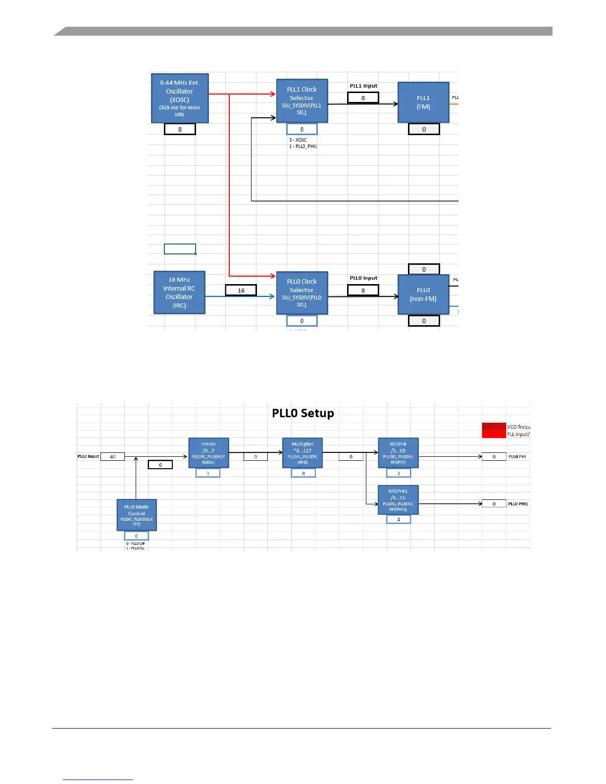
Figure 27. PLL0 source to XOSC
Next, configure PLL0. Click on the PLL0 block to forward automatically to the PLL0 tab. This is the tab
that sets up the PLL0_PHI frequency. The PLL0 Input block of the figure below shows that PLL0
detects the 40 MHz XOSC as its source frequency.
Figure 28. PLL0 calculator
Configure the dividers to achieve 200 MHz. The correct configuration can be achieved by trial and error,
but the MPC5777C clock calculator provides a lookup table in the pll0_phi tab, as shown in the
following figure.

 Loading...


