Clock tool example use case: Configure eMIOS to 60 MHz PLL1 with MPC5777C_264MHz
MPC5777C Clock Calculator Guide, Rev. 1, 12/2018
NXP Semiconductors 23
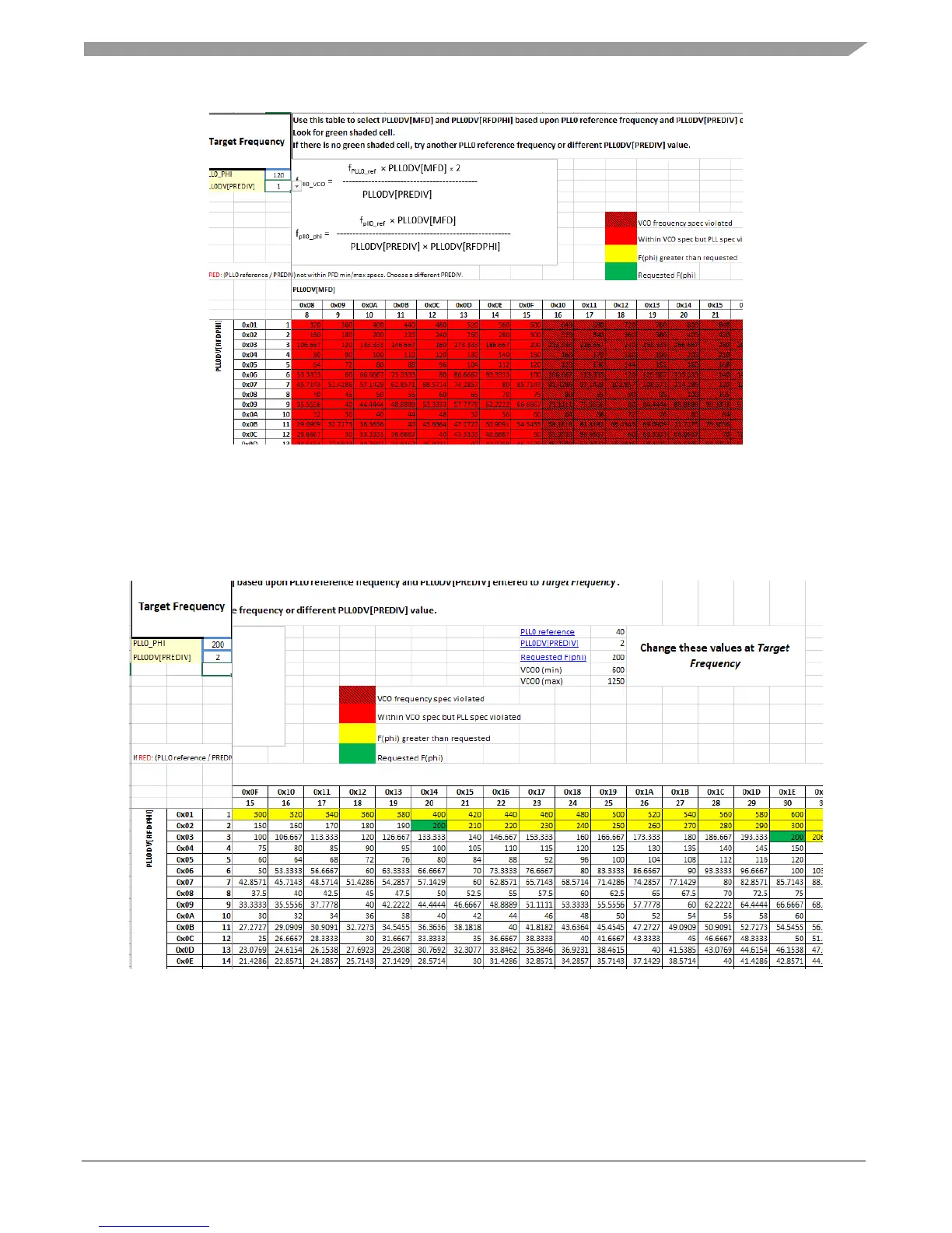
Figure 29. PLL0_PHI reference table
The PLL0 reference field is the frequency of the PLL0 input, in this case the 40 MHz XOSC. Set the
target frequency and PREDIV values. This example will target 200 MHz and change PREDIV to 2. The
values and shading in the lookup table will automatically change to fit these new settings. In the figure
below, the table has changed and circled are the modified settings.
Figure 30. PLL0_PHI table with new settings
The cells shaded green means there are two divider combinations that can achieve exactly 200 MHz
given an input frequency of 40 MHz and a PREDIV of 2. This example will use a MFD of 20 and a
RFD of 2, but before configuring the PLL0 tab, it is worth noting what happens if the output PLL
frequency is out of range.

 Loading...


