Clock tool example use case: Configure eMIOS to 60 MHz PLL1 with MPC5777C_264MHz
MPC5777C Clock Calculator Guide, Rev. 1, 12/2018
24 NXP Semiconductors
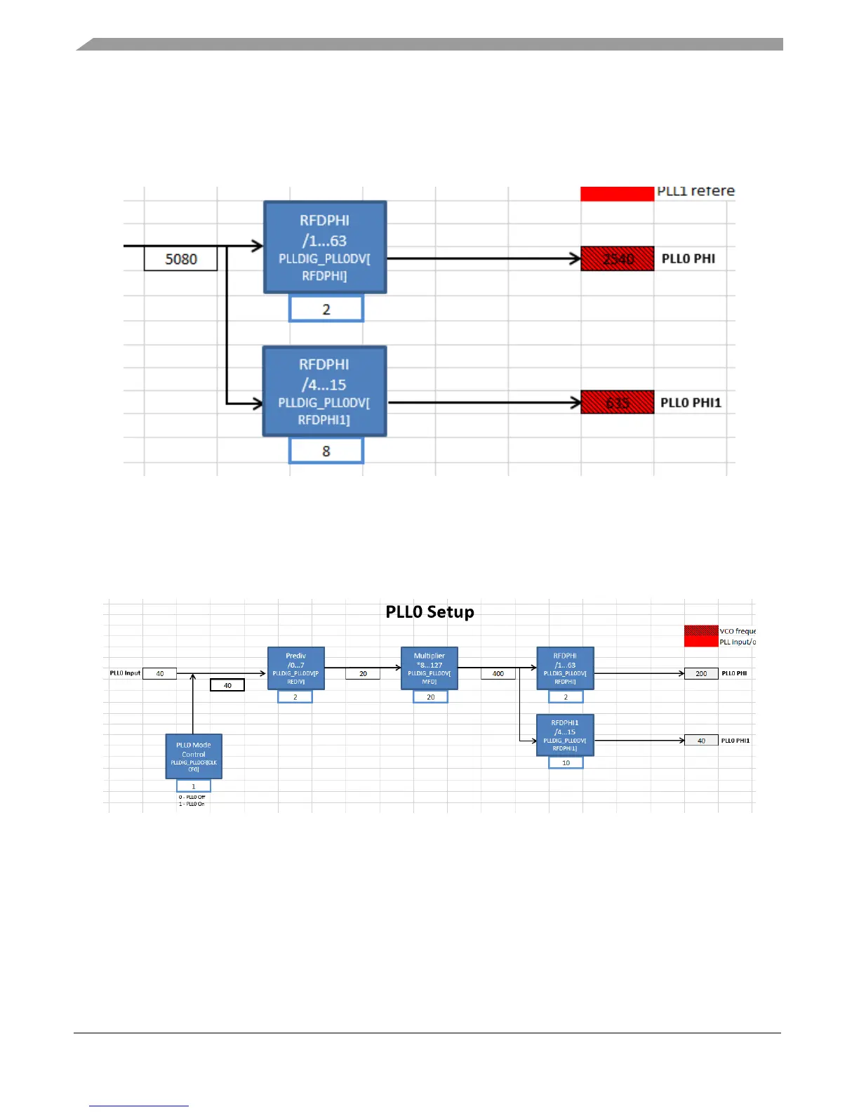
In the following figure, the PLL has been configured so that the output frequency is 5.08 GHz. This
obviously exceeds the maximum hardware spec of 200 MHz. The associated voltage controlled
oscillator (VCO) frequency, which can be back-calculated from PLL0_PHI also exceeds the maximum
VCO spec of 1250 MHz. Therefore, the output is crosshatched and shaded red.
Figure 31. When PLL0_PHI exceeds VCO and PLL spec
Now let’s configure the PLL correctly. Turn on the PLL in the PLL0 tab by setting the PLL0 Mode
Control block to 1, set Prediv to 2, Multiplier to 20, and RFDPHI to 2. As shown in the next figure, the
output PLL0_PHI is 200 MHz and the cell remains unshaded, meaning the configuration fits within
spec. Also, set RFDPHI1 to 10 so that PLL0_PHI1 is 40 MHz. This output will be the source of PLL1.
Figure 32. PLL0_PHI configured to 200 MHz
Go back to Tree to observe that the PLL0_PHI frequency is now 200 MHz and PLL0_PHI1 is 40 MHz.

 Loading...


