Clock tool example use case: Configure eMIOS to 60 MHz PLL1 with MPC5777C_264MHz
MPC5777C Clock Calculator Guide, Rev. 1, 12/2018
NXP Semiconductors 25
Figure 33. PLL0_PHI propagated to Tree
3.2.3.
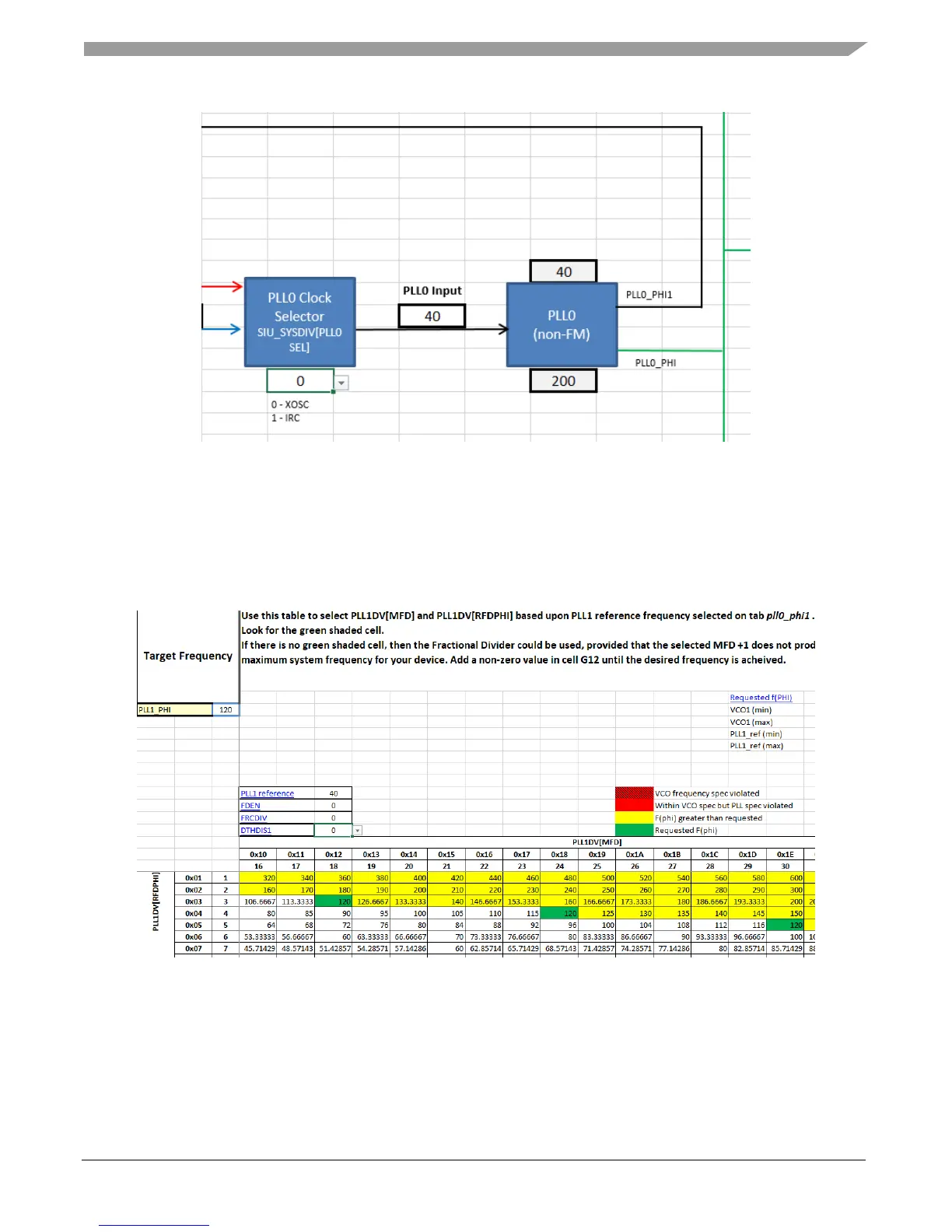
Configure PLL1
Next, configure PLL1_PHI to 120 MHz using PLL0_PHI1 as the source. Change the PLL1 Clock
Selector block to 1 to select PLL0_PHI1 as the source of PLL1. Much like the case with PLL0, you can
use the pll1_phi reference table to find the proper dividers, as shown in the figure below.
Figure 34. PLL1_PHI table for 120 MHz
There are three settings that achieve exactly 120 MHz. This example will use an MFD of 18 and an
RFDPHI of 3. In the PLL1 tab, turn on the PLL and enter these settings much in the same manner as for
PLL0, as seen in the following figure.

 Loading...


