Clock tool example use case: Configure eMIOS to 60 MHz PLL1 with MPC5777C_264MHz
MPC5777C Clock Calculator Guide, Rev. 1, 12/2018
26 NXP Semiconductors
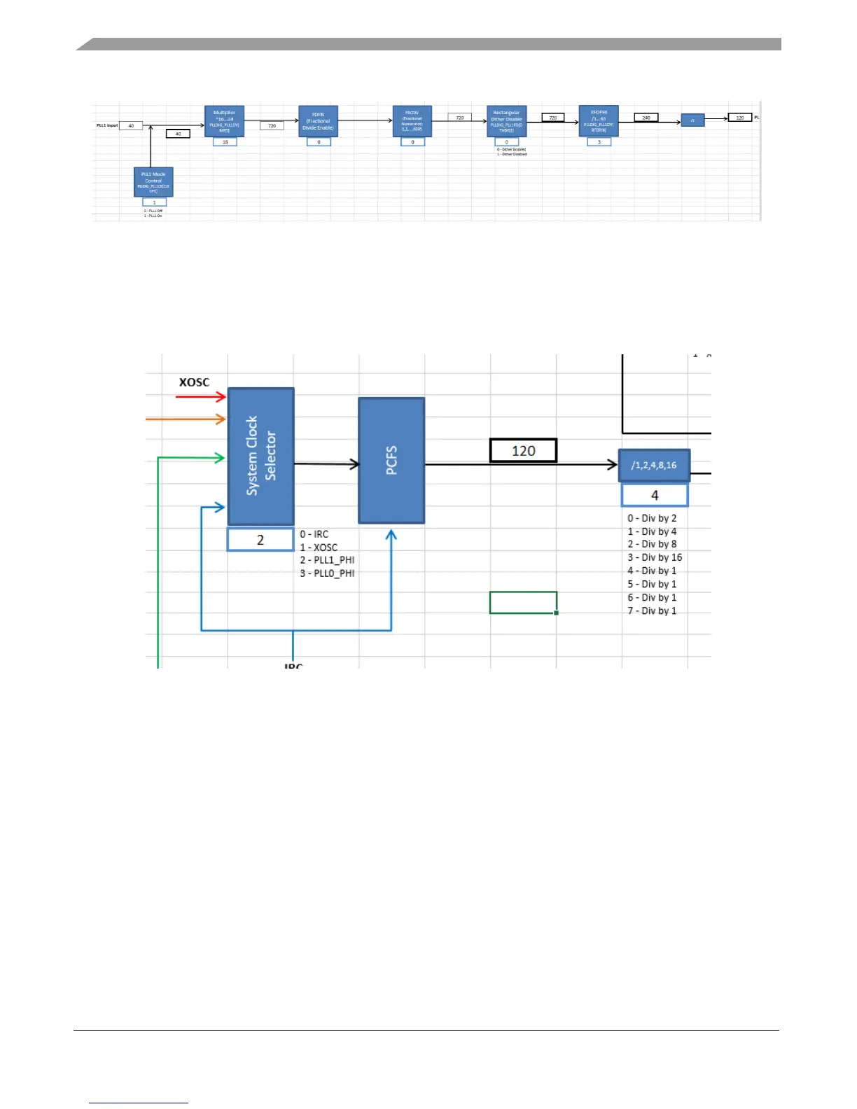
Figure 35. PLL1 at 120 MHz
3.2.4.
Finish Setting PER_CLK
With the PLLs properly configured, change the system clock source to PLL1_PHI by changing the
System Clock Selector value to 2.
Figure 36. System clock following PLL1_PHI
The PCFS block stands for Progressive Clock Frequency Switch. This is a feature supported in the
MPC5777C to smooth the transition of the system clock from one clock source to another. The block
here is just a visual representation for the user to know that the system clock filters through the
progressive clock switch before propagating to the various system clock domains. PCFS takes IRC in
this diagram because its logic is organized in terms of IRC cycles. You can find more information on the
progressive clock switch in the application note AN5304. The linked application note explains how to
configure the MPC574xP, but its general principle can be extrapolated to the MPC5777C.
Set the system clock divider to divide by 1 so that CORE_CLK is 120 MHz. There are multiple bitfield
values that does the job. This example will use the MPC5777C’s reset value of 4. See the following
figure.

 Loading...


