PF 33 MT - PF 46 MT
Installation and connections
EN - 11
FIG. 4
180
160
140
120
100
80
60
180
160
1
0
0,1
2
3
4
5
6
140
120
100
80
60
S
2
1
3
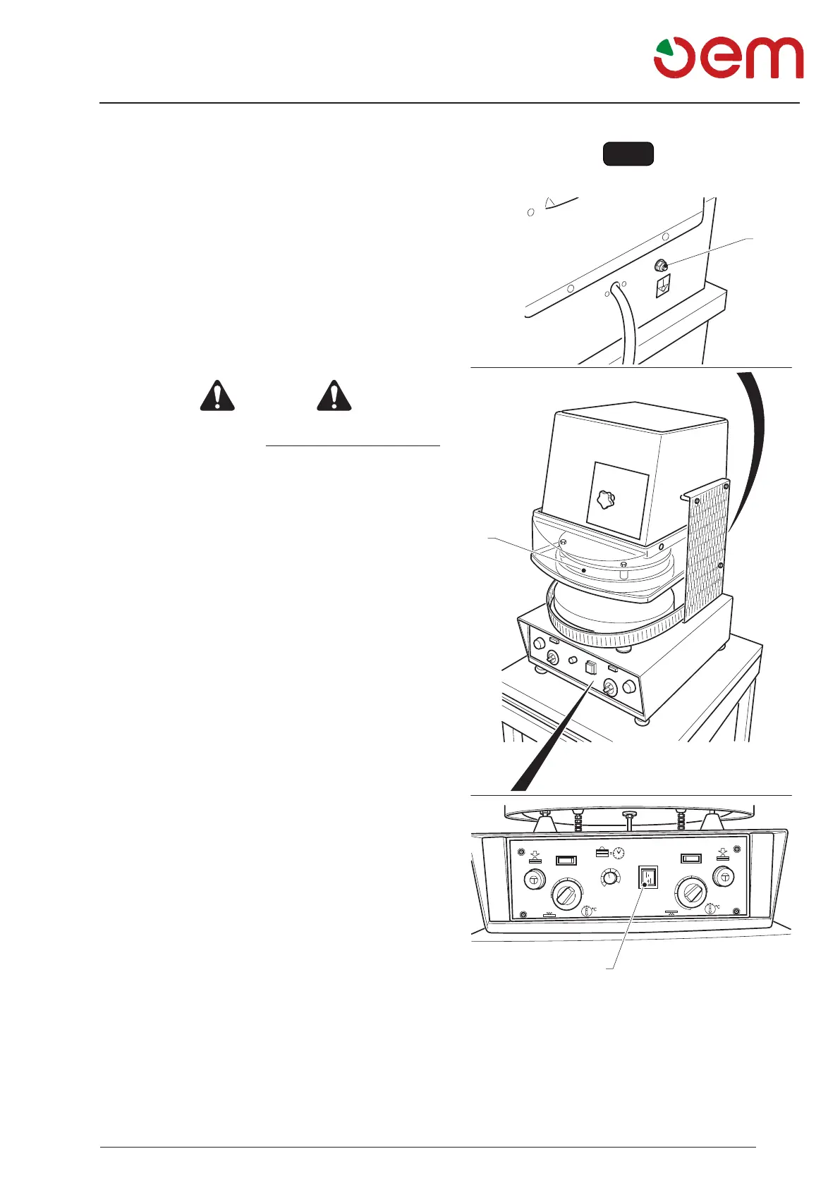
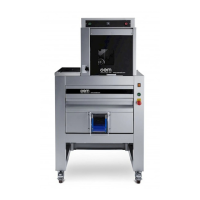
3.3.a - CONTROL OF A CORRECT ELECTRICAL
CONNECTION (FIG. 4)
For the connection 400 V three phase, it is necessary to
check if the engine rotation is right, to do this proceed
as follows:
• Turn the cut-out switch placed on the upper machine
side to “ON”.
• Press the main switch (1) “Position I”, it lights up.
• If the connection is correct, the upper dish (2) will rise.
• If the connection is incorrect, the dish (2) will lower,
therefore, immediately turn off the machine by set-
tingthe switch (1) to “0” and turn offthe switch located
upstream of the machine
DANGER
Before making any change in the electrical connec-
tion, make sure that the DISCONNECTING SWITCH
is disconnected (line not energized), then: two of
the three phases on the cutout switch shall be inverter-
ted, then, make sure the functioning is correct.
3.3.b - UNIPOTENTIAL CONNECTION (Fig. 4)
The machine is provided with a screw (3) for unipotential
connection.
To make the connection, unscrew the screw nut (3),
connect the cable of the unipotential net to the screw
and tighten the nut again.
3.4 - FIRST START (Fig. 4)
Start the machine as indicated in the paragraph “Ma-
chine Functioning” and make sure all units properly
function.