Chapter 11: IBM - Graphics
11-2
2
6
2
2
93 entered as CHR$(93)
+ 64
32
+16
+8
+4
2
+1
128
2
7
2
5
2
4
2
3
2
1
2
0
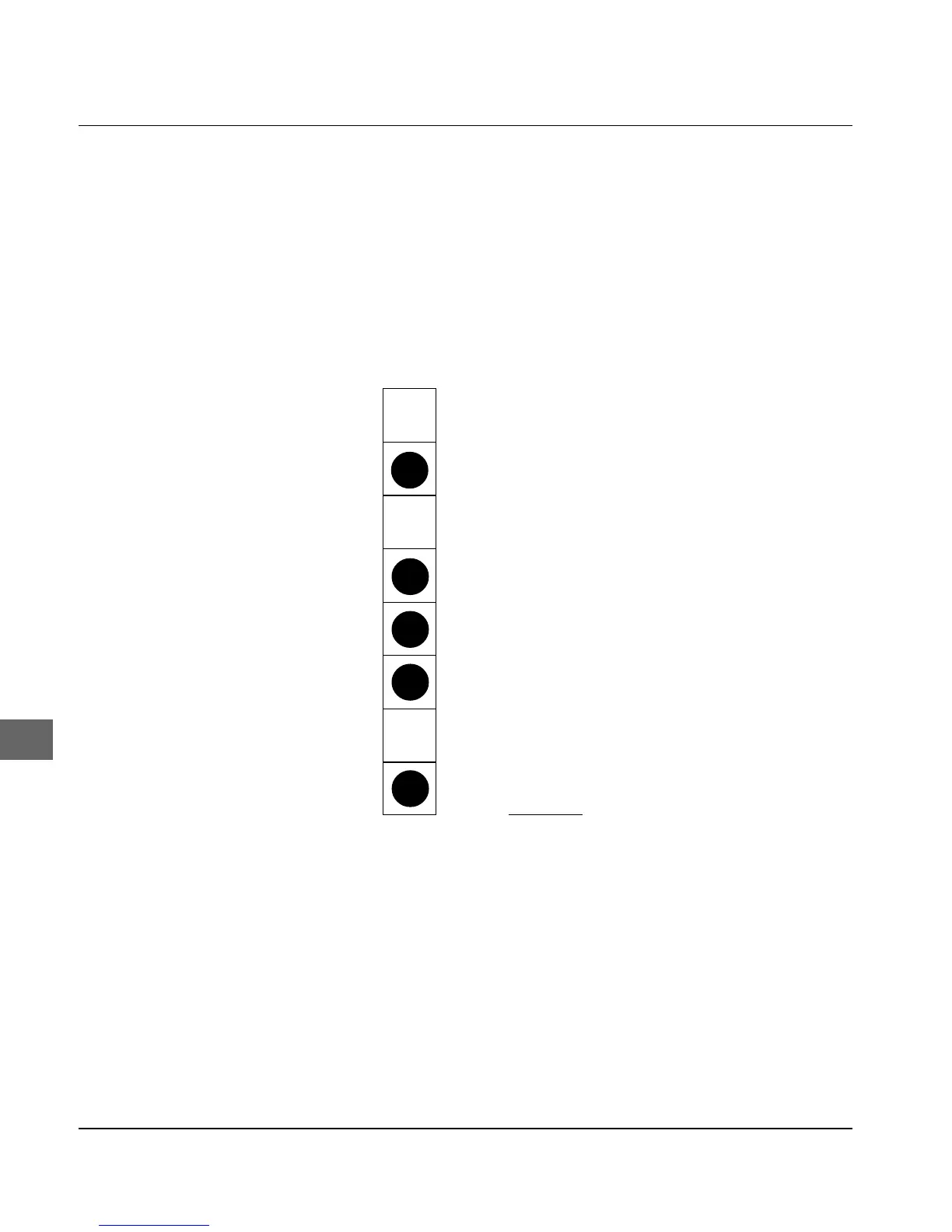
Picture a byte as a column of 8 dots each corresponding to a bit.
With bit image graphics, data in columns of this kind are printed
next to each other. If you are writing your own program, you must
convert the bit-by-bit dot pattern into a decimal or hexadecimal for-
mat and send it byte-by-byte to the printer.
The following diagram shows how you determine the decimal va-
lue of a certain pin pattern.
Position value Binary value
In the diagram, the positions with the values 64, 16, 8, 4 and 1 are
intended to be printable dots. Only these figures are added together
to determine the value for this byte.
Your printer is capable of representing 8-dot graphics in order also
to be able to print graphics which have been created for 9-pin dot
matrix printers. For this is used a technique in which two pins toge-
ther correspond to one pin of the 9-pin dot matrix printer in order to
achieve a comparable and distortion-free image.