D-2
Appendix D: Interface Data
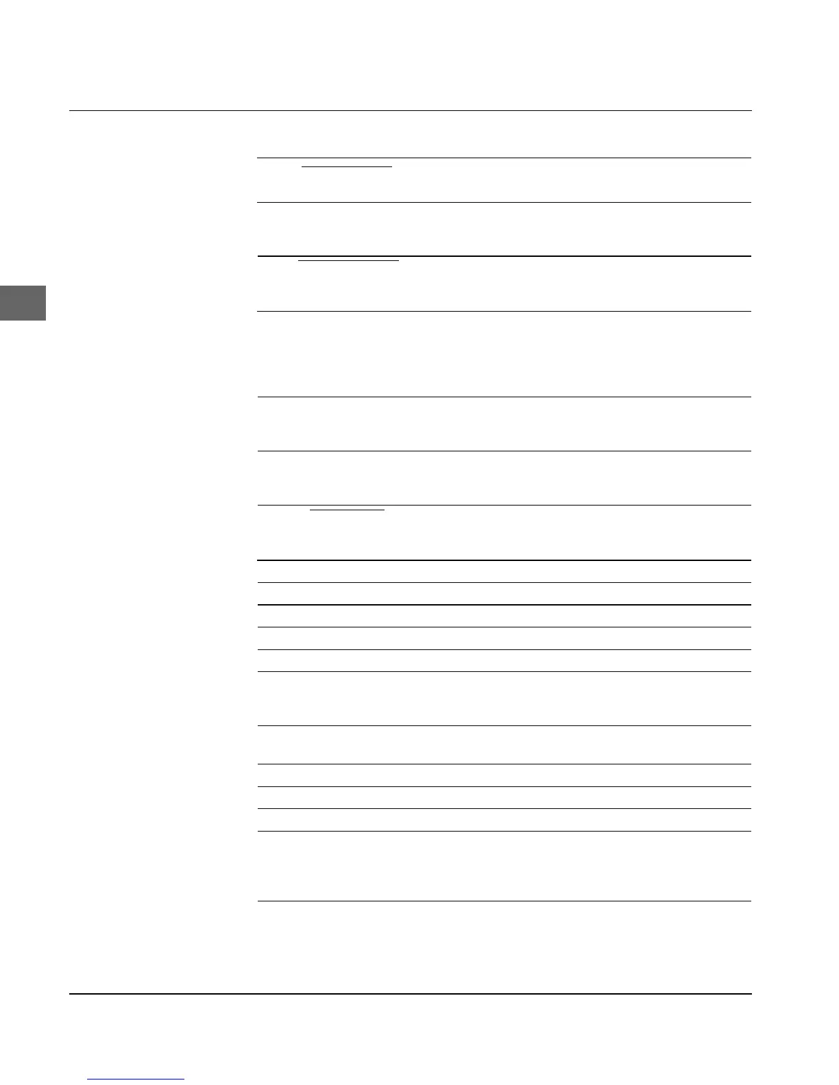
Pin Signal Direction Description
1 DATA STROBE To printer When the signal changes from low
to high level, input data is sampled.
2-9 DATA BIT 1-8 To printer Input data lines. The High level
represents 1, the Low level repre-
sents 0
10 ACKNOWLEDGE From printer The High level of this signal
indicates completion of data input
or function operation.
11 BUSY From printer The High level of this signal
indicates that the printer cannot
receive data. The low level of the
signal indicates that the printer is
ready for receiving data.
12 PAPER END From printer The High level of this signal
indicates that a paper end has
been detected.
13 SELECT From printer The High level of this signal
indicates that the printer is in the
select mode (ON LINE).
14* AUTOFEED To printer In EPSON emulation a Low level
of the signal activates the auto line
feed.
15 -- -- Not assigned.
16 0 V -- Signal ground
17CHASSIS GROUND -- Frame ground
18* + 5 V From printer + 5-volt supply (max. 50 mA).
19-30 0 V -- Twisted pair return for pins 1 to 11.
31 ** I-PRIME To printer Signal Low: Printer controller is
initialised. The low level should be
held for more than 0.5 ms.
32 FAULT From printer When the paper end is detected this
signal changes from High to Low.
33 0 V -- Signal ground
34 -- -- Not assigned.
35 -- -- Not assigned.
36 SELECT-IN To printer The High level of this signal
indicates that the printer can only
be selected and deselected using
DC1 and DC3 control codes.
* Pin 14 and 18 can be activated/deactivated by menu item Auto Feed XT or Pin
18.
Pin Description