D-20
Appendix D: Interface Data
Protocol: X-ON/X-OFF
Printer status line: TD
HP 24541B Printer Menu Settings
SD.A 9
SD.B 10
RD.A 3
RD.B 18
GND 19
SSD+ 3
SSD- 21
SD+ 4
SD- 22
RD+ 6
RD- 24
RS+ 7
RS- 25
CS+ 9
CS- 27
DM+ 11
DM- 29
TR+ 12
TR- 30
–
+
–
+
–
+
–
X-ON/X-OFF
Serial I/F Option
Protocol
Busy Line
DSR Signal Invalid
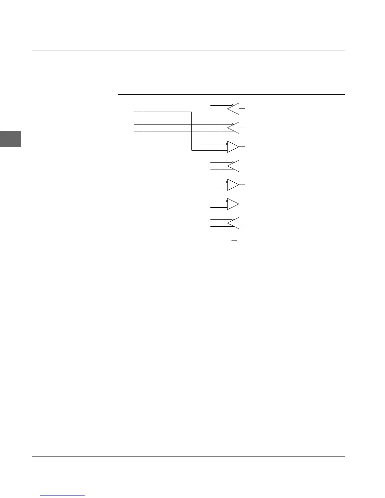
In this circuit example (connecting a HP 24541B interface board
with the RS-422A interface of the printer) the ports SD-A, Pin 9, and
SD.B, Pin 10 are connected to ports RD+, Pin 6 and RD-, Pin 24 of
the printer interface, as shown in example 6. In this circuit example
(HP 24541B interface board connected to the RS-422A interface of
the printer) the ports SD.A, Pin 9 and SD.B, Pin 10 are connected to
the ports RD+, Pin 6 and RD-, Pin 24 of the printer interface. These
are the two transmission lines for the print data.
The two lines for the printer status are established by connecting
the ports RD.A, Pin 3 and RD.B, Pin 18 with the ports of the printer
interface TR+, Pin 12 and TR-, Pin 30.
Please note the Ready/Busy-lines in this circuit: although port
RD.B, Pin 18 on host side is specific for the RS-422A interface, the
second line is connected to port RD.A, Pin 3 of the RS-232C inter-
face. This ensures correct transmission of data with most applica-
tions, but it cannot be guaranteed for all applications.
Diagram 7