D-19
Appendix D: Interface Data
Protocol: Ready/Busy
Ready/Busy-Line (printer): SD
HP 24541B Printer Menu Settings
SD.A 9
SD.B 10
CB (CTS) 5
RD.B 18
GND 19
SSD+ 3
SSD- 21
SD+ 4
SD- 22
RD+ 6
RD- 24
RS+ 7
RS- 25
CS+ 9
CS- 27
DM+ 11
DM- 29
TR+ 12
TR- 30
–
+
–
+
–
+
CC (DSR) 6
DTR
Ready/Busy
Serial I/F Option
Protocol
Busy Line
DSR Signal Invalid
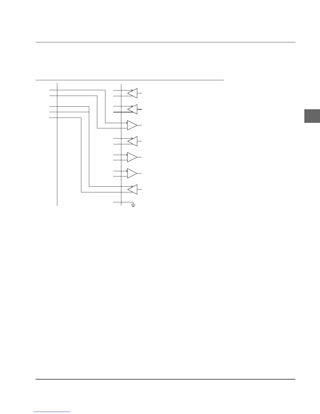
In this circuit (connection of a HP 24541B interface board with RS-
422A-Interface of the printer) the ports SD.A, Pin 9 and SD.B, Pin 10 are
connected to the ports RD+, Pin 6 and RD-, Pin 24 of the printer inter-
face. These are the two lines for the transmission of the print data.
The two lines for the Ready/Busy-Signal are created by connecting
ports CB (CTS), Pin 5 and RD.B, Pin 18 to the ports TR+, Pin 12 and
TR-, Pin 30 of the printer interface. Additionally a connection to CC
(DSR), Pin 6, is established on the host side from CB (CTS), Pin 5.
Looking at the two Ready/Busy-lines please note the following: al-
though the port RD.B, Pin 18 on the host side is specific for the RS-
422A interface, the second line is connected to the ports CB (CTS),
Pin 5 and CC (DSR), Pin 6 of the RS-232C interface. This ensures the
correct transmission of data with many applications, but it cannot
be guaranteed for all applications.
When printer and software status signals X-ON and X-OFF are
evaluated by an application while this circuit example is used, the
correct data transmission with this type of interface board on the
host side is not possible.
Diagram 6