D-25
Appendix D: Interface Data
Interface Protocol Power Number of SP1 SP2 SP3 SP4 SP5 Menu Settings
Source Lines
Current Loop CBD * passive 2 B B B A A **
Current Loop CBD * passive 4 B B C A A **
Current Loop CBD * active 2 B BBBA **
Current Loop CBD * active 3 B B C B B **
* CBD = Centronics Blocked Duplex
** Protocol setting in menu will not be applied.
Rearrange the jumpers only when the printer is turned off.
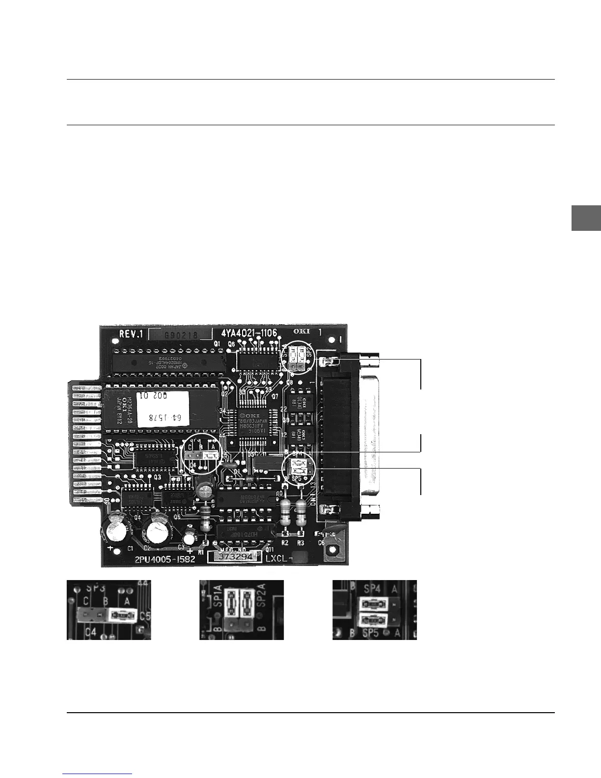
SP 3: Pin Assignment SP1: Protocol Selection SP4: Power Source/
Receive Loop
SP2: RS-232C/Current Loop SP5: Power Source/
Send Loop
SP1/
SP2
SP3
SP4/
SP5
The component layout diagram of the printed circuit board for the
coresident serial RS-232C/Current Loop interface and the arrange-
ment of the jumpers (SP1 - SP5) is shown in the following figures.
Component layout
diagram