D-36
Appendix D: Interface Data
Interface Test
Connect the test loop plug described below to the interface in order
to perform an interface test.
Select Yes in the Diagnostic Test menu to enable the interface test
of the printer.
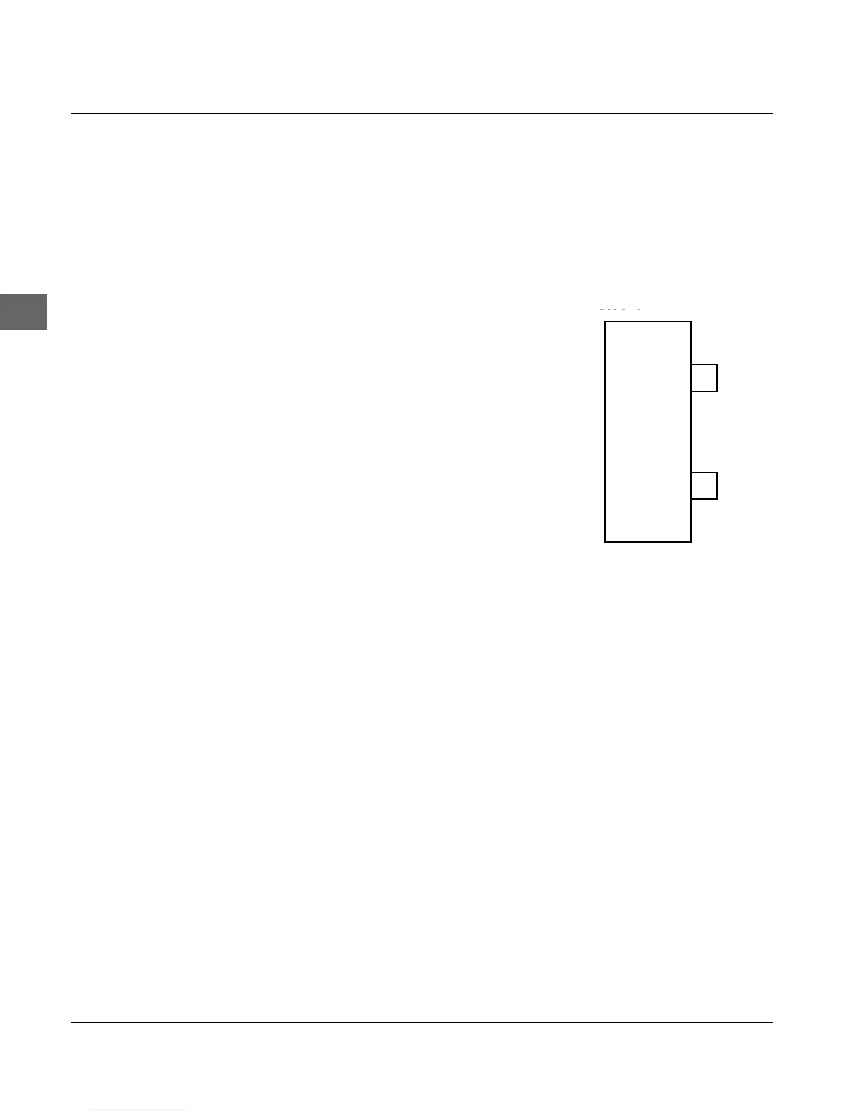
● Connect the test loop plug to
the connector of the serial in-
terface.
● Connect short-circuit jump-
er SP2 to side B and SP3 to
side B to select the Current
Loop operating mode. Plug
SP4 into side B and SP5 into
side A to activate the inter-
face connection with two
transmission lines and a
power source on the printer
side. This circuit is equiva-
lent to diagram 14.
● Turn the printer on. The printer buffer, interface driver and re-
ceive loop functions on the serial interface are now tested. On
completion of this test all characters are printed in a test pattern.
The result is printed as follows:
The message CORESIDENT SERIAL I/F F/W xx.xx YR4064-
1578 LOOP TEST will be printed, where xx.xx is replaced by the
current ROM version.
The printer checks the buffer and prints RAM = GOOD, if no error
occurred or RAM = BAD, if an error occurred during the memory
test.
The signal logic is also tested. The message CURRENT LOOP I/F =
GOOD is printed if no error was detected. If an error occurred, the
message CURRENT LOOP I/F = BAD is printed.
Contact your local dealer, if the message CURRENT LOOP I/F =
BAD is printed.
Stecker
10
18
(Current Loop)
19
7
D-
B+
B-
SG
Canon DB-25S or equivalent