%Serial Interface Test
Serial Interface Test
After youve made an interface cable for your computer and printer, you may want to spend a few
extra minutes making a test connector. This test connector can be used to monitor the operation
of the interface by isolating the printer from the computer. With the test connector installed, the
printer transmits and receives its own signal.
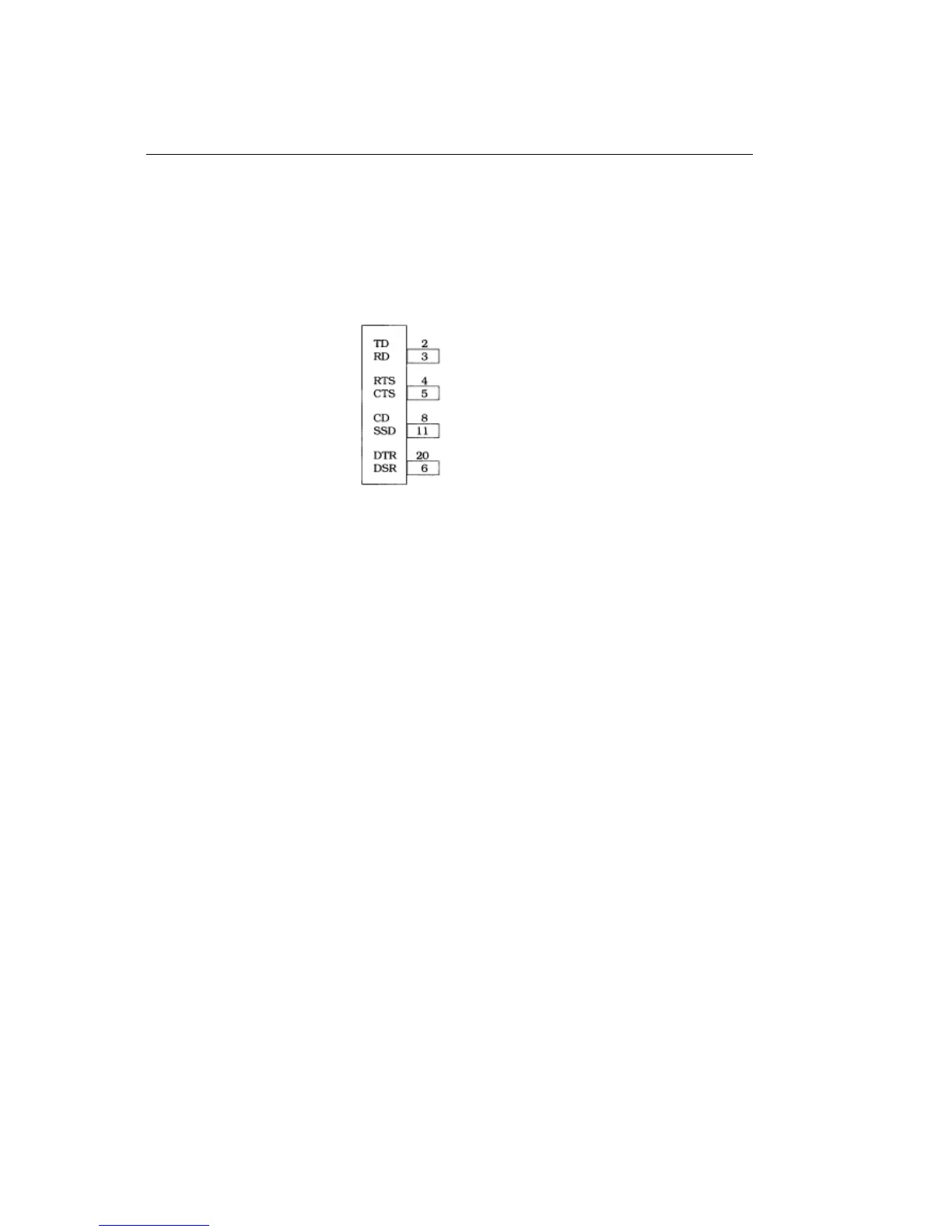
To make the connector, jumper the following pins on an RS232-C (DP-25P) plug:
To run the test:
1.Place the printer in the circuit test mode by entering the Menu Select Mode and specifying Yes for
the item Diagnostic Test in the group Serial Interface.
2.Turn the printer OFF.
3.Remove the computer cable from the serial interface receptacle and replace it with the test
connector.
4.Turn the printer on. This will start the test. The following will happen as the test proceeds:
First, the printer will check the memory function and the signal logic. If both are functioning
properly, it will print the following:
LOOP TEST
RAMGOOD
I/FGOOD
If either function is faulty, the printer will print the message BAD beside that function, rather than
GOOD.
If BAD is printed, call you dealer for assistance.
Next, the printer will generate a test pattern, send the data through its transmit and receive circuits,
and write the data to its message buffer. It will then print the stored data. The test pattern
consists of the ASCII characters equivalent to decimal values 32 to 126. This process repeats
until you stop the test.
5.Press the Mode button to stop the test.
6.Remove the test connector and replace the computer cable.
7.Turn off the printer and enter the Menu Select Mode by holding down the FONT button while
ML 380 ( 96-02-03 )