9-2 94MS20 Rev. B4
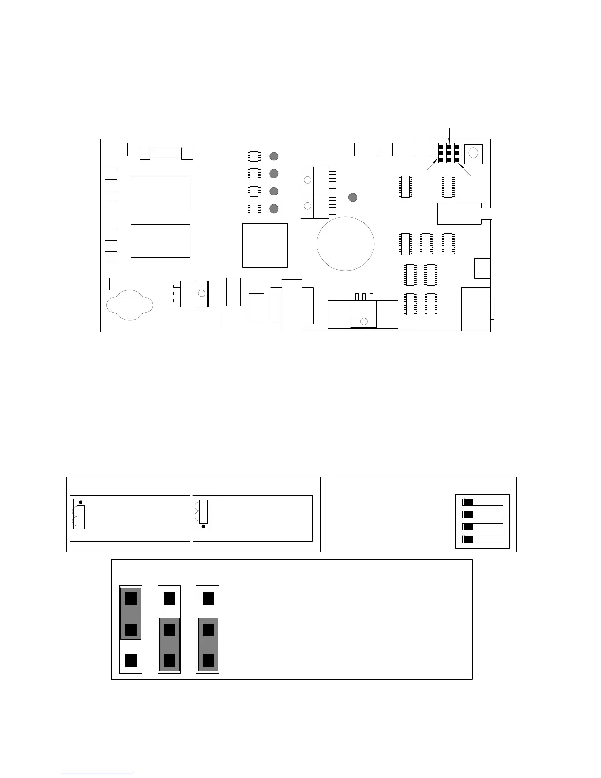
AL 13 Control Board (64MV427C2)
1) AC COM
2) Ballast COM
3) Lamp COM
4) Blower COM
5) Blower HOT
6) Medium Cap Input
7) High Cap Input
8) Low Cap Input
9) Lamp Lead HOT
10) Ballast AC HOT
11) Incoming AC HOT
12) **Voltage Selection
Jumpers** see NOTE A
13) Ground
14) Shutter Motor +
15) Shutter Motor -
16) Shutter Switch 2 +
17) Shutter Switch 2 -
18) Shutter Switch 1 +
19) Shutter Switch 1 -
DS1) POWER
DS2) BLOWER
DS3) MED POWER
DS4) HIGH POWER
DS5) SHUTTER MOTOR
A) Idle Adjustment
B) External Interlock
C) **External Operation Switches**
see NOTE B
D) Control Din (to integrator)
NOTE A: TERMINAL 12 Voltage Selection Switch
Connector must be
in this position for
120V
Connector must be
in this position for
220V
NOTE B Test Switches OFF ON
1 Power ON/OFF
2 High Expose
3 Medium Expose
4 Low Expose
1
2
3
4
5
6
7
8
9
10 11 13 14 15 16 17 18 19
10 Amp Fuse
DS1
DS2
DS3
DS4
DS5
12
A
B
C
D
JP1
JP2
JP3
JP1 JP2 JP3 JUMPER SETTING
JP1 UP
JP2 UP
DOWN
JP3 UP
DOWN
Duel Shutter Switch Operation
Single Shutter Switch Operation
Not Using External Interlock
Using External Interlock
50Hz Operation
60Hz Operation
DOWN