9-10 94MS20 Rev. B4
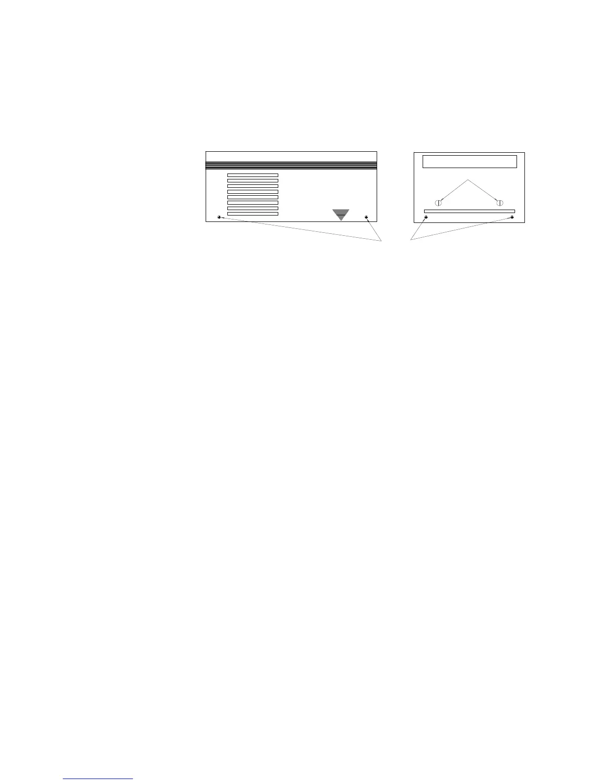
AL 9, AL 13 Cover Removal
• Place the light on its top and remove the hood and filter assembly.
• Place the light on a table with the shutter flat against the table and remove
the safety glass. Then remove the two screws from each of the four sides
and remove the cover.
Screws
OLITE AL13
Safety Glass Thumbscrews
Path of Power to the P.C.Board
The power circuit can be easily traced from where the power cord enters
the corner of the unit and immediately connects with 2 (two) wire nuts to
black (V~ hot) and white (V~ common). The circuit travels through the
black wire to the thermostat, then through the safety glass switch and
returns as a brown wire to the P.C. Board as incoming V~ (HOT). The
V~ common circuit travels through the white wire to the other safety
glass switch and returns as a yellow wire to the P.C. Board as incoming
V~ common.
Interlock Systems
The internal interlock system serves two purposes. The first is for operator
safety by protecting the safety glass. This glass filters short UV radiation
and covers the high voltage lamp terminals. This interlock also protects
from overheating, by traveling through the thermostat by the reflector.
There is also an outlet on the side marked “INTERLOCK”. This external
interlock inhibits exposures when installed. It is not, however, related to
the internal interlock.
The internal interlock is a loop that travels through the light, passing
through two safety glass switches and a thermostat. This interlock is in
series with the input power to the P.C. Board. When this interlock is
open all power is cut to the P.C. Board.
The first place to check for an opening in the circuit is the glass switches
(see Component Layout Diagram for location). If both switches check
good, then check the thermostat. This is a closed loop and can be traced
with an Ohmmeter with the AL9/AL14 unplugged.