51
SD-505
Troubleshooting
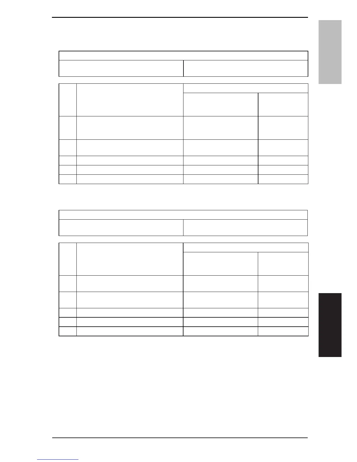
10.2.5C11B5: Side staple 1 drive failure
10.2.6C11B6: Side staple 2 drive failure
10.2.7C11D0: Crease motor drive failure
Relevant electrical parts
Staple unit 1
Staple unit 2
SD control board (SDCB)
Step Action
WIRING DIAGRAM
Control signal
Location
(Electrical
component)
1
Check the staple units 1 and 2 connectors
for proper connection and correct as nec-
essary.
——
2
Check staple units 1 and 2 for proper drive
coupling, and correct as necessary.
——
3 Staple units 1 and 2 operation check — —
4 Change staple units 1 and 2 — —
5 Change SDCB — —
Relevant electrical parts
Crease motor (M10)
Crease roller home position sensor (PS22)
SD control board (SDCB)
Step Action
WIRING DIAGRAM
Control signal
Location
(Electrical
component)
1
Check the M10 connector for proper con-
nection and correct as necessary.
——
2
Check M10 for proper drive coupling and
correct as necessary.
——
3 M10 operation check SDCB PJ3-1 to 2 SD-505 C-7
4 PS22 I/O check, sensor check SDCB PJ2-3 (ON) SD-505 C-7
5 Change SDCB — —
Y108482-2 Service Manual
Field Service Ver. 2.0 Jan. 2008 10. Malfunction code