Bode 100 User Manual
40
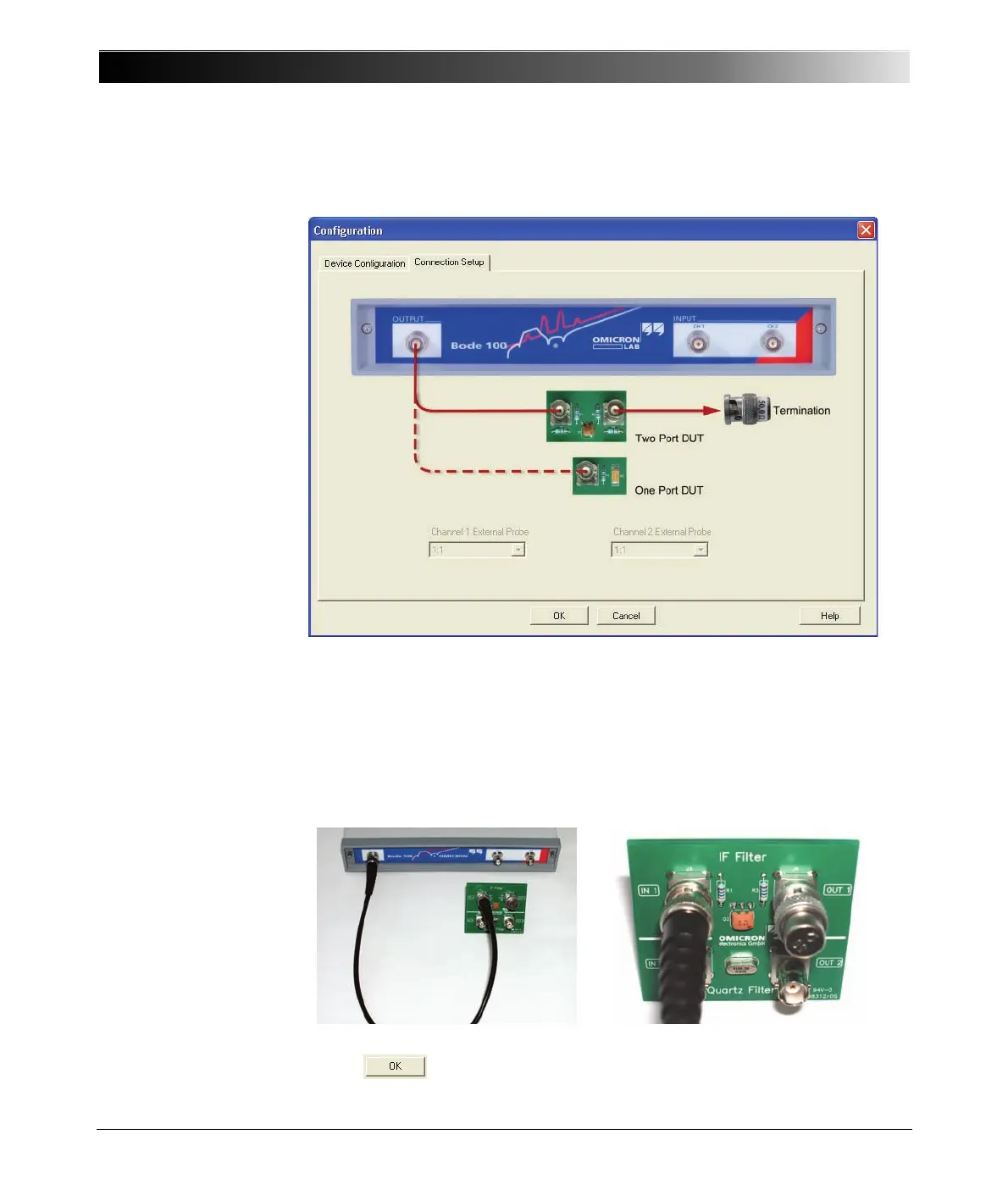
6. Click the Connection Setup tab.
The connection diagram shows how to connect the DUT to the Bode 100.
Hint: In the Impedance/Reflection mode, the channel 1 and channel 2
inputs are not used. Consequently, the External Probe boxes are
unavailable.
7. Connect the output of the Bode 100 to the input of the IF filter and the BNC
50 Ω load to the output of the IF filter as shown.
8. Click to close the Configuration window.