CP TD12/15 User Manual
38 OMICRON
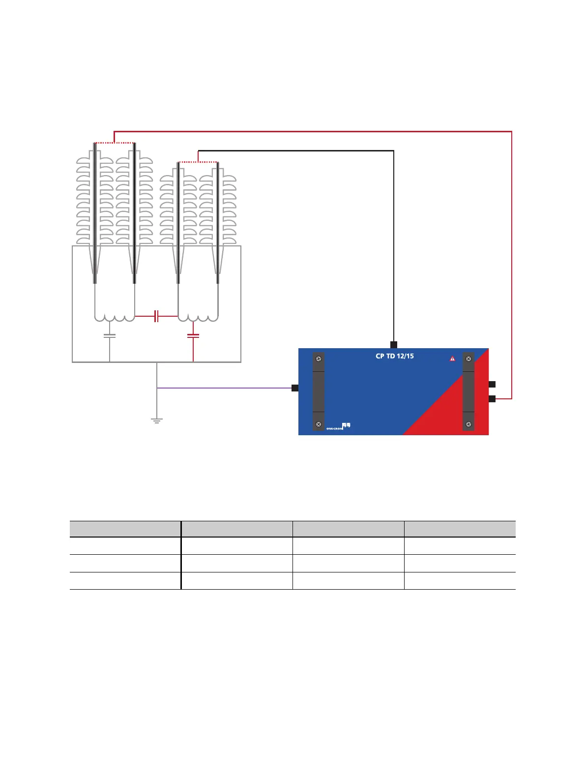
For the measurement of C
L
, the setup has to be changed. The HV-output has to be connected to the LV-
side and IN A to the HV-side (see Figure 5-4 blow).
Figure 5-4: CP TD12/15 connected to a two-winding transformer for the measurement of
C
HL
and C
L
With this setup 3 configurations are available as well (see Table 5-2 below). As C
HL
has been measured
before, usually only C
L
is measured in this second measurement.
Table 5-2: Modes available with a measurement setup as seen in Figure 5-4
Mode IN A Ground Result
UST-A Measured Guarded C
HL
GSTg-A or GSTg-(A+B) Guarded Measured C
L
GSTg-B Measured Measured C
HL
+ C
L
LVHV
C
HL
C
L
C
H
IN A
IN B
HV output
HV output
Measurement
ground

 Loading...


