20
Logic Functions Section 1-5
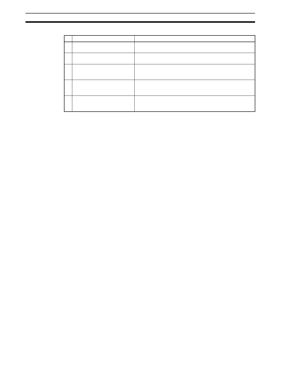
Data That Can Be Set for Additional Outputs
Note Turns OFF (0) when one of the errors shown in 7-3 Error History occurs.
IMPORTANT When additional output data is set, safety output terminals will reflect the out-
put status even in Idle Mode.
Note (1) An additional output can be used only when the output terminals are set
as a single channel.
(2) An ON delay or OFF delay can be set for safety output terminals even
when an additional output is set.
Additional output data Description
S Same value as safety output
terminal
Outputs the same value as any safety output terminal.
S Inverse value of safety output
terminal
Outputs the inverse value of any safety output terminal.
Reset required indication Outputs a 1-Hz pulsing signal to trigger a reset input. The sig-
nal is output when resetting is enabled for one or more termi-
nals from among all the safety input terminals.
RUN Status Flag Outputs the operating mode.
0: Not RUN mode
1: RUN mode
Normal Status Flag Outputs the status.
0: Error (See note.)
1: Normal

 Loading...


