Section 8 Setting data
8-8
Setting data
• The decimal point position is determined by the selected sensor in
the case of temperature input, and by scaling in the case of analog
input. If "Display digits after PV decimal point" is set to "OFF" for
temperature input, digits following the decimal point are not shown.
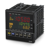
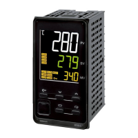
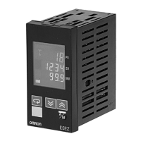
At "Display 1" "Display 2", the bank number appears in Display 3.
At "Display 2", the MV appears in Display 3.
"Display screen selection" (Display adjustment level) can be used to
set the display sequence to Display 1/Display 2, Display 2/Display 3,
Display 1 only, or Display 2 only.
The initial setting is Display 2/Display 3; PV/SP/MV, PV/SP/Bank No.
● Related setting data
"Input * type" (Input initial setting level) (P.8-36)
"Input* temperature units" (Input initial setting level) (P.8-37)
"Scaling input value 1", "Scaling display value 1", "Scaling input
value 2", "Scaling display value 2", "Decimal point position" (Input
initial setting level) (P.8-37)
"Remote SP upper limit", "Remote SP lower limit" (Input initial
setting level) (P.8-38)
"PV decimal point display" (Input initial setting level) (P.8-39)
"SP upper limit", "SP lower limit" (Control initial setting level) (P.8-43)
"SP mode" (Adjustment level) (P.8-14)
"PV/SP display screen selection" (Display adjustment level) (P.8-60)
• This is used to monitor the remote SP while in local SP mode.
• In remote SP mode, the remote SP can be monitored in Display 2 of
the PV/SP screen.
Setting
Monitor range Units
PV
"Appendix Sensor input setting ranges ·
Indicator (control) ranges" (P.A-4)
EU
Setting or monitor range Units
Default value
PV
Local SP: SP lower limit to SP upper limit EU 0.0
Remote SP: Remote SP lower limit to
remote SP upper limit
Note that the SP limits are in effect.
EU -
Reference
Reference
Remote SP monitor
rsp
Local SP, control mode set to standard control with remote SP
CH
Function
Monitor
Monitor range Units
Remote SP lower limit to remote SP upper limit
Note that the SP limits are in effect.
EU

 Loading...

