Section 8 Setting data
8-78
Setting data
• Use this setting to select Mode 0 or Mode 1 for the MV change rate
limit.
• When Mode 1 is selected, the MV change rate limit only functions
with respect to increases in the MV.
● Related information
"5.2 Control functions ■ PID sets" (P.5-12)
● Related setting data
"MV change rate limit (heat)", "MV change rate limit (cooling)"
(Adjustment level) (P.8-19)
• These settings are normally used at the default values.
• "AT calculated gain" specifies the gain used when PID values are
calculated during AT. A smaller gain provides greater adaptability,
while a larger gain provides greater stability.
• "AT hysteresis" is used to set the value of hysteresis for ON/OFF
switching during the limit cycle while AT is being run.
• "Limit cycle MV amplitude" is used to set the MV amplitude during
the limit cycle while AT is being run.
• This is effective when P
≠ 0.00 in standard control, or when closed is
selected in proportional control.
• "Temporary AT execution judgement deviation" is used to judge if
temporary AT is excute or not for running temporary AT. When AT is
excuted while, the deviation is greater than the set value, temporary
AT runs.
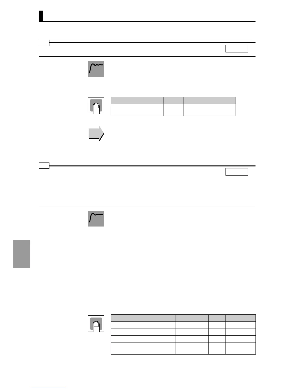
MV change rate limit mode
orlm
CH
l.exc
Function
Setting
Setting range Units Default value
0: Mode 0
1: Mode 1
− 0
Reference
Reference
AT calculated gain
AT hysteresis
Limit cycle MV amplitude
Temporary A.T. execution judgement deviation
at-g
at-h
lcma*
tate*
* Control mode key: heating/cooling control
and position proportional control
(floating). During cascade heating/cooling
control, only channel 1 is displayed.
CH
l.exc
Function
Setting
Setting Setting range Units
Default value
AT calculated gain 0.1 to 10.0 − 1.0
AT hysteresis 0.1 to 9.9 %FS 0.2
Limit cycle MV amplitude 5.0 to 50.0 % 20.0
Temporary AT execution
judgement deviation
0.0 to 100.0 %FS 10.0
 Loading...


