Appendix
A-26
Appendix
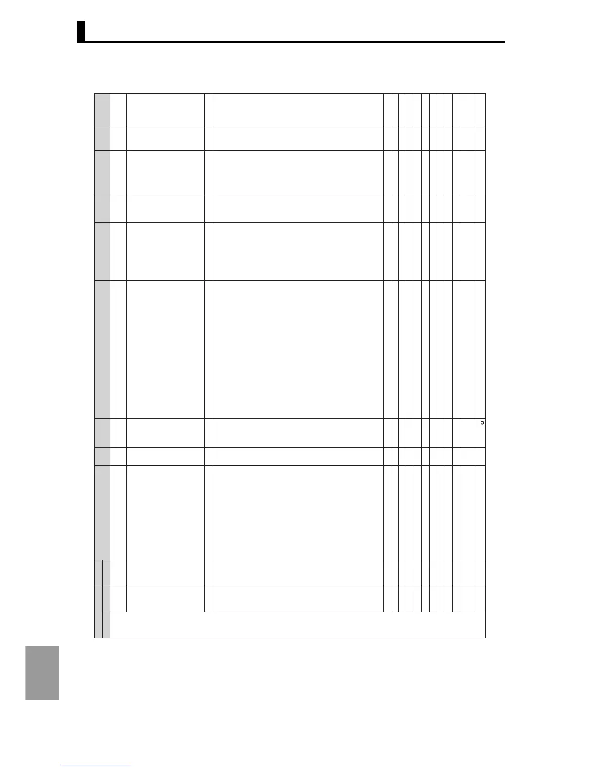
CompoWay/F
Setting data
Attributes
Variable type
Address Address
Modbus
Character Setting (monitor) value Character
Default
value
Decimal point
position
Units
Set value
D2 −
0000
0001
0002
0003
0004
0005
0006
0007
0008
0009
000A
000B
000C
−
−
−
1200
1202
1204
1206
1208
120A
120C
120E
1210
1212
1214
1216
1218
−
−
init
pf1
pf2
pf1.1
pf1.2
pf1.3
pf1.4
pf1.5
pf2.1
pf2.2
pf2.3
pf2.4
pf2.5
ch-n
ramm
cmo
OFF (0)
ON (0)
H'00000000: OFF (0)
H'00000001:RUN (1)
H'00000002:STOP (2)
H'00000003:R-S (3)
H'00000004:ALLR (4)
H'00000005:ALLS (5)
H'00000006:AT (6)
H'00000007:BANK (7)
H'00000008:A-M (8)
H'00000009:PFDP (9)
Same as PF1 setting
H'00000000: Disabled (0)
H'00000001:PV/SP/Bank setting is possible
(SP) (1)
H'00000002:PV/SP/MV setting is possible
(SP) (2)
H'00000003:PV/Deviation Monitor only (3)
H'00000004:Proportional band (P) setting is possible (4)
H'00000005:Integral time (I) setting is possible (5)
H'00000006:Differential time (D) setting is possible (6)
H'00000007:Alarm 1 setting is possible (7)
H'00000008:Alarm upper limit 1 setting is possible (8)
H'00000009:Alarm upper limit 1s etting is possible (9)
H'0000000A:Alarm 2 setting is possible (10)
H'0000000B:Alarm upper limit 2 setting is possible (11)
H'0000000C:Alarm upper limit 2 setting is possible (12)
H'0000000D:Alarm 3 setting is possible (13)
H'0000000E:Alarm upper limit 3 setting is possible (14)
H'0000000F:Alarm upper limit 3 setting is possible (15)
H'00000010:Alarm 4 setting is possible (16)
H'00000011:Alarm upper limit 4 setting is possible (17)
H'00000012:Alarm upper limit 4 setting is possible (18)
H'00000013:Banks
.
setting is possible (19)
Same as PF1 monitor / setting 1
Same as PF1 monitor / setting 1
Same as PF1 monitor / setting 1
Same as PF1 monitor / setting 1
Same as PF1 monitor / setting 1
Same as PF1 monitor / setting 1
Same as PF1 monitor / setting 1
Same as PF1 monitor / setting 1
Same as PF1 monitor / setting 1
H'00000001 to H'00000004 (1 to 4)
Backup mode:BKUP (0)
RAM write mode:RAM (1)
-1999 to 9999
off, on
off, run,
stop, r-s,
allr, alls,
at, bank,
a-m, pfdp
Same as above
0 to 19
0 to 19
0 to 19
0 to 19
0 to 19
0 to 19
0 to 19
0 to 19
0 to 19
0 to 19
1 to 4
bkup to ram
-1999
to
9999
OFF
A-M (8)
R-S (3)
1
0
0
0
0
1
0
0
0
0
*1
BKUP (0)
0
−
−
−
−
−
−
−
−
−
−
−
−
−
−
−
−
−
−
−
−
−
−
−
−
−
−
−
−
−
−
−
−
Common
Common
Common
CH
CH
CH
CH
CH
CH
CH
CH
CH
CH
Common
Common
Common
Parameter intitialization
PF1 setting
PF2 setting
PF1 monitor / setting item 1
PF1 monitor / setting item 2
PF1 monitor / setting item 3
PF1 monitor / setting item 4
PF1 monitor / setting item 5
PF2 monitor / setting item 1
PF2 monitor / setting item 2
PF2 monitor / setting item 3
PF2 monitor / setting item 4
PF2 monitor / setting item 5
Number of enabled channels
RAM write mode
Move to calibration level
Advanced function setting level
"H' -" indicated in set values (monitor values) are values set by communication (monitor).
*1 .... The initial setting for the number of enabled channels varies depending on the model, and is the maximum value of the configuration.
 Loading...


