63
Safety Device Function Blocks Section 3-5
Machine’s Dangerous Area is on the Opposite Side of the Operator (Figure 2):
Note In the above example, limit switch 1 (S1) is wired to Si0 on the G9SP-series
Controller and limit switch 2 (S2) is wired to Si1. Set the dual channel mode
for local inputs in the G9SP-series Controller to dual channel complementary.
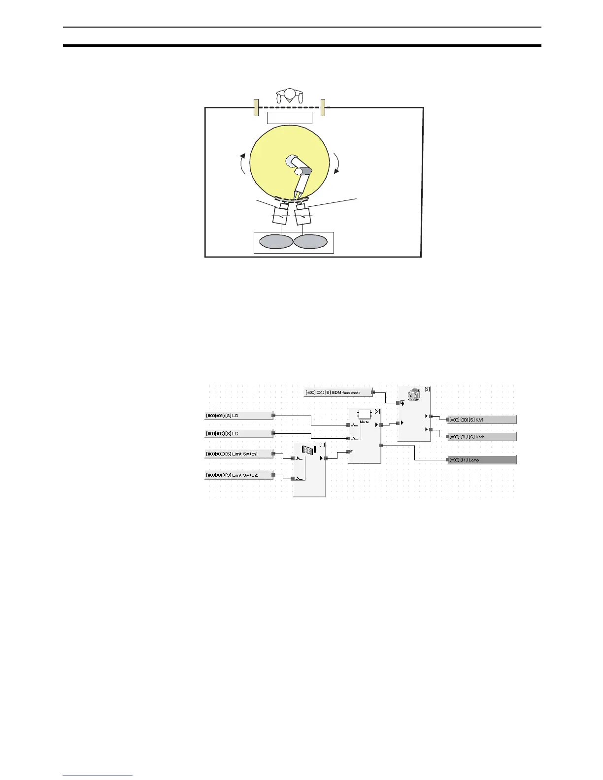
Program Example
Limit switches 1 and 2 connected to Si0 and Si1 on the G9SP-series Control-
ler are connected to Muting Signal 11 of the Muting function block through the
Safety Gate Monitoring function block.
Note Limit switches 1 and 2 are set to the dual channel complementary setting for
local inputs to evaluate the input data from the two switches.
Note The Safety Gate Monitoring function block is used as a function block for the
limit switches. Set the input type of the Safety Gate Monitoring function block
to Dual Channel Complementary (1 pair).
Muting Sequence
1. In figure 1 above, N.O. limit switch 1 is OFF and N.C. limit switch 2 is ON.
In addition, the light curtain is not obstructed, so the Output Enable signal
is ON. Muting Signal 11, which inputs the dual channel complementary
signal for limit switches 1 and 2, goes OFF.
2. As the robotic arm rotates, limit switch 1 goes ON and limit switch 2 goes
OFF as shown in figure 2. Muting Signal 11, which inputs the dual channel
complementary signal for limit switches 1 and 2, goes ON, so muting is en-
abled, and the Muting Status goes ON.
3. At this point, the Output Enable signal is kept ON even if the Safety Light
Current is obstructed so the operator can access the work platform.
Guard fence
Light curtain
Light curtain
Operator
Limit switch 1
(N.O. contact)
Limit switch 2
(N.C. contact)
ON
OFF
Si1
Si0
Work platform
G9SP-series
Controller
 Loading...


