n
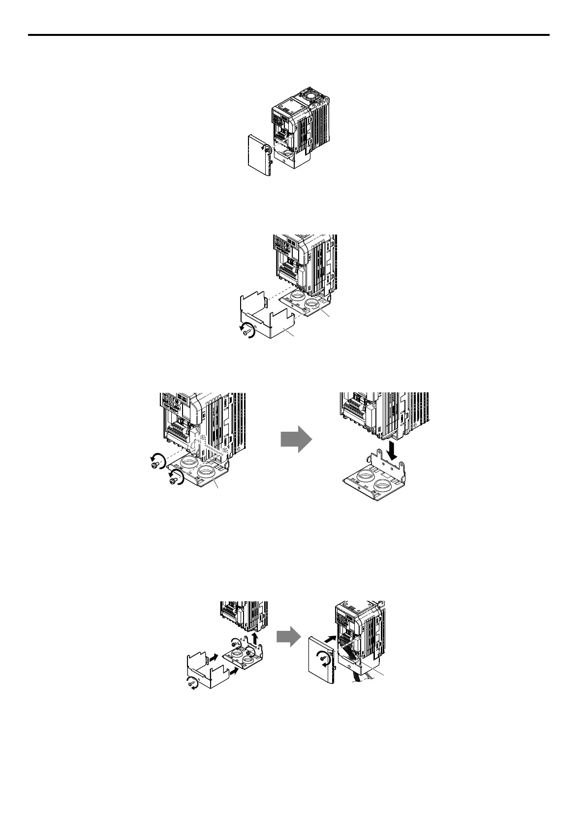
Removing the Protective Covers on a NEMA Type 1 Design
1.
Loosen the screw on the front cover to remove the front cover.
Figure 8.10 Remove the Front Cover on a NEMA Type 1 Drive
2.
Loosen the screw on the terminal cover (Figure 8.11, B) to remove the terminal cover and expose the conduit
bracket (Figure 8.11, A).
A
B
Figure 8.11 Remove the Terminal Cover on a NEMA Type 1 Drive
3.
Loosen two screws attaching the conduit bracket (Figure 8.12, A) to remove.
A
Figure 8.12 Remove the Conduit Bracket on a NEMA Type 1 Drive
n
Reattaching the Protective Covers
Pass
power wiring and control signal wiring through the exit holes on the bottom of the conduit bracket of the drive. Place
power wiring and control signal wiring in separate conduits. Properly connect all wiring after installing the drive and
connecting other devices. Reattach all protective covers when wiring is complete.
A
A – Pass power wiring and control signal wiring through different exit holes at the bottom of the drive.
Figure 8.13 Reattach the Protective Covers and Conduit Bracket on a NEMA Type 1 Drive
8.4 Installing Peripheral Devices
158
SIEP C710606 33A OYMC AC Drive – J1000 User Manual
 Loading...


