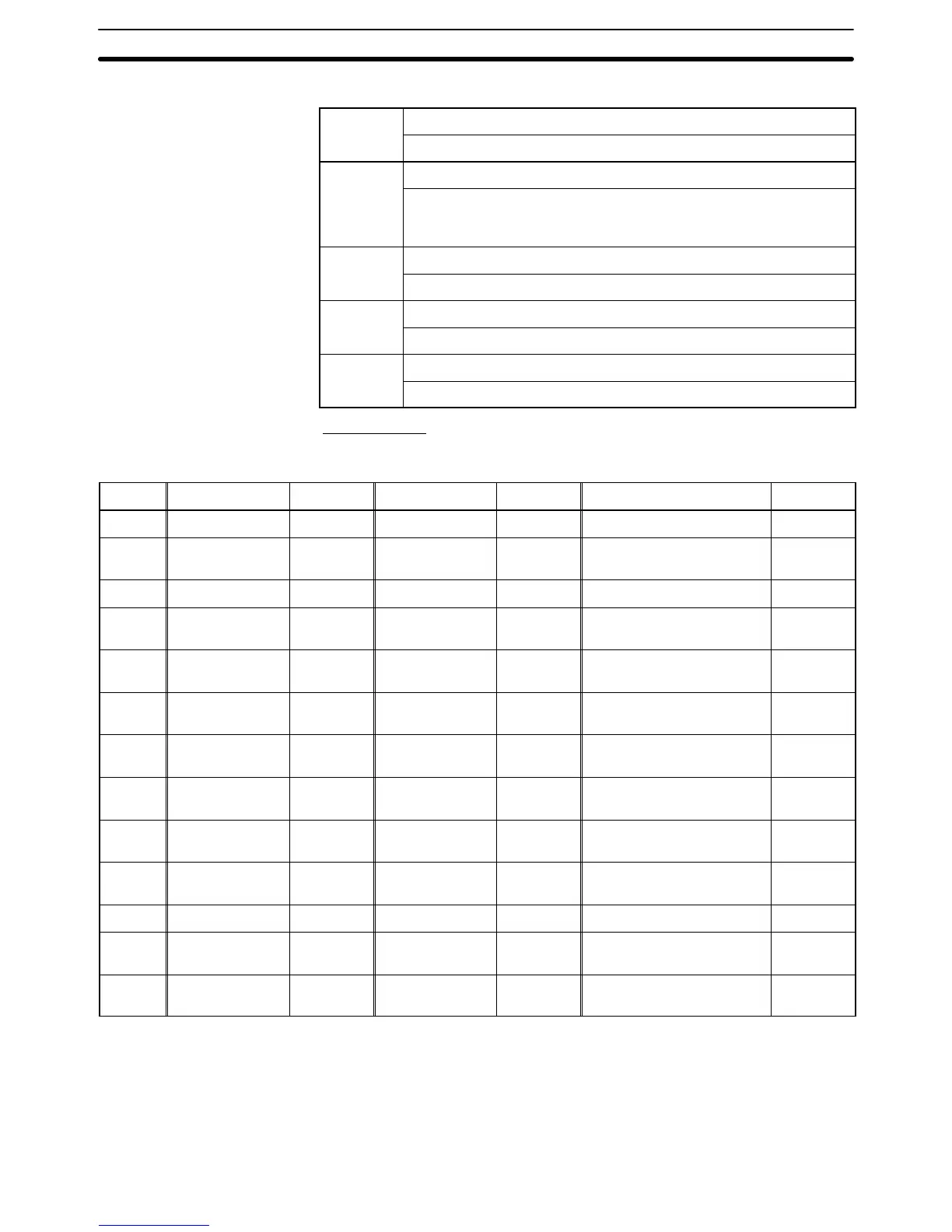
Possible Settings
Property
Meaning
Function
None/Switch screen/Alarm
Function of the bit memory table entry
When None is set, nothing will happen even if the host bit allocated for
the table entry turns ON.
Description
Indicates the settings particular to each function.
PC
Up to 16 characters of text
Comment
Comment that describes the meaning of a bit memory table entry
Allocated Bits
Bits can be allocated for bit memory table entries in the following host (PC)
areas.
Symbol C-series PCs Allocation CV-series PCs Allocation CS/CJ-series PCs Allocation
None IR Area OK CIO Area OK CIO Area OK
H HR Area OK --- --- HR Area
Not for
Host Link
A AR Area OK Auxiliary Area No AR Area OK
L LR Area OK --- --- LR Area
*1
Not for
Host Link
T
TC Area,
Timer PVs
No
Timer Area,
Timer PVs
No
TC Area,
Timer PVs
No
TU --- --- --- ---
TC Area,
Timer Completion Flags
Not for
Host Link
C
TC Area,
Counter PVs
No
Counter Area,
Counter PVs
No
TC Area,
Counter PVs
No
CU --- --- --- ---
TC Area,
Counter Completion Flags
Not for
Host Link
W --- --- --- --- WR Area
Not for
Host Link
TK --- --- --- --- Task Flags
Not for
Host Link
D DM Area OK DM Area OK DM Area OK
E
EM Area
*2
,
current bank
OK
EM Area,
current bank
Not for
Host Link
EM Area,
current bank
Not for
Host Link
E0_ to
EC_
--- --- --- ---
EM Area,
EM banks 0 to C
Not for
Host Link
*1: LR 00000 to LR 00199 are converted to CIO 01000 to CIO 01199.
*2: The EM Area is supported only by the C200HX/HG/HE(-Z)E PCs.
The Auxiliary Area of the CVM1 and CV-series PCs is allocated to system func-
tions, and it cannot be used for purposes other than system use.
The range of each memory area differs according to the PC. Refer to Appendix D
PC Memory Maps on page 435.
Common Attributes