5 - 9
5 Designing the Power Supply System
NX-series EtherCAT Coupler Unit User’s Manual (W519)
5-3 Designing the I/O Power Supply System
5
5-3-1 I/O Power Supply Method
5-3 Designing the I/O Power Supply Sys-
tem
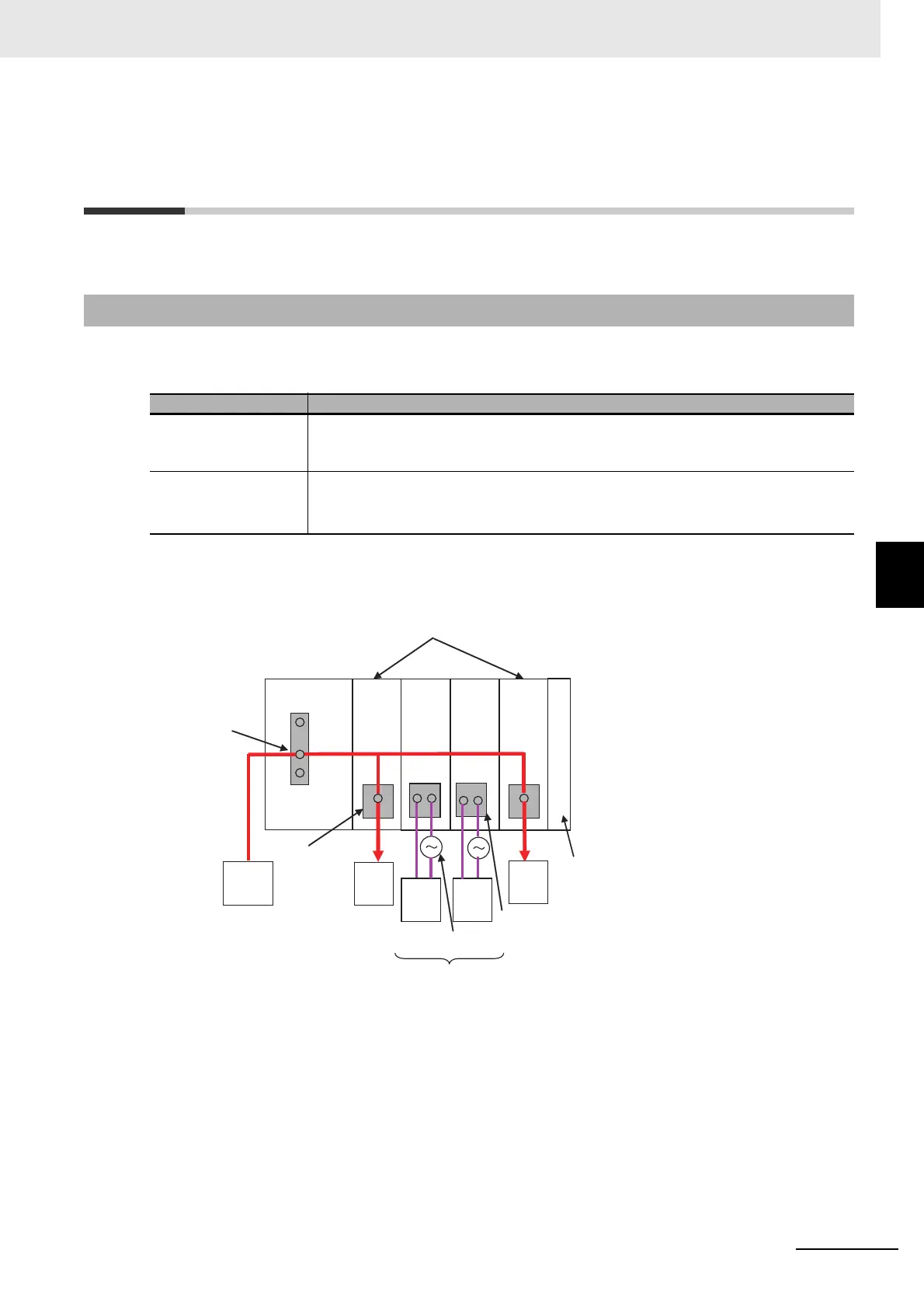
This section describes how to design the I/O power supply to the EtherCAT Slave Terminal.
There are the following two methods to supply the I/O power supply to the EtherCAT Slave Terminal
depending on the type and model of the NX Units.
Refer to the user’s manuals for individual NX Units or to the NX-series Data Reference Manual (Cat.
No. W525) for the power supply method for specific NX Units.
An example is shown below.
5-3-1 I/O Power Supply Method
Supply method Description
Supply from the NX bus Power is supplied through the NX bus connectors by connecting an I/O power supply
to the I/O power supply terminals on the EtherCAT Coupler Unit or Additional I/O
Power Supply Units.
Supply from external
source
Power is supplied to the Units from an external source.
I/O power is supplied by connecting an I/O power supply to the terminal blocks on the
Units.
External
output
device
Terminal block
Supplied from external source.
I/O power supply (AC)
External
output
device
External
output
device
External
input
device
Terminal block
I/O power
supply
(DC)
I/O power supply
terminals
EtherCAT
Coupler Unit
Supplied from the NX bus.
DC Input
Unit
Relay
Output
Unit
Relay
Output
Unit
Transistor
Output Unit
End Cover